Calculators & guides only — no articles or blog noise.
Engine Compression Ratio Calculator
Static and dynamic compression ratio from the four volumes you can actually measure — chamber, gasket, deck and piston
Embed this calculatorFree · no API key · keep the attribution link
Copy the snippet below to embed this calculator on your site. The attribution link must stay intact and dofollow (no rel="nofollow"). Browse all embeddable calculators
<div class="ttq-embed" style="max-width:100%;margin:0 auto;">
  <iframe src="https://testtalkhq.com/embed/engine-compression-ratio-calculator/?theme=light&utm_source=embed" width="100%" height="980" frameborder="0" loading="lazy" scrolling="no" title="Engine Compression Ratio Calculator — TestTalkHQ" style="border:0;max-width:100%;width:100%;"></iframe>
  <p style="font:400 13px/1.4 system-ui,sans-serif;text-align:center;margin:6px 0 0;">Powered by the <a href="https://testtalkhq.com/engine-compression-ratio-calculator/?utm_source=embed&utm_medium=referral&utm_campaign=calculator_embed&utm_content=engine-compression-ratio-calculator" target="_blank" rel="noopener">Online Engine Compression Ratio</a> from <a href="https://testtalkhq.com/?utm_source=embed&utm_medium=referral&utm_campaign=calculator_embed&utm_content=engine-compression-ratio-calculator" target="_blank" rel="noopener">TestTalkHQ</a></p>
</div>
Everything above is arithmetic. The accuracy lives in the inputs, and four of them cannot be looked up: the piston-to-deck clearance, the finished bore, the compressed gasket thickness and the chamber volume of the head actually in front of you. A catalogue figure for any of those is a starting assumption, not a measurement — which is why the bench tools below matter more to the answer than the calculator does.
Deck clearance
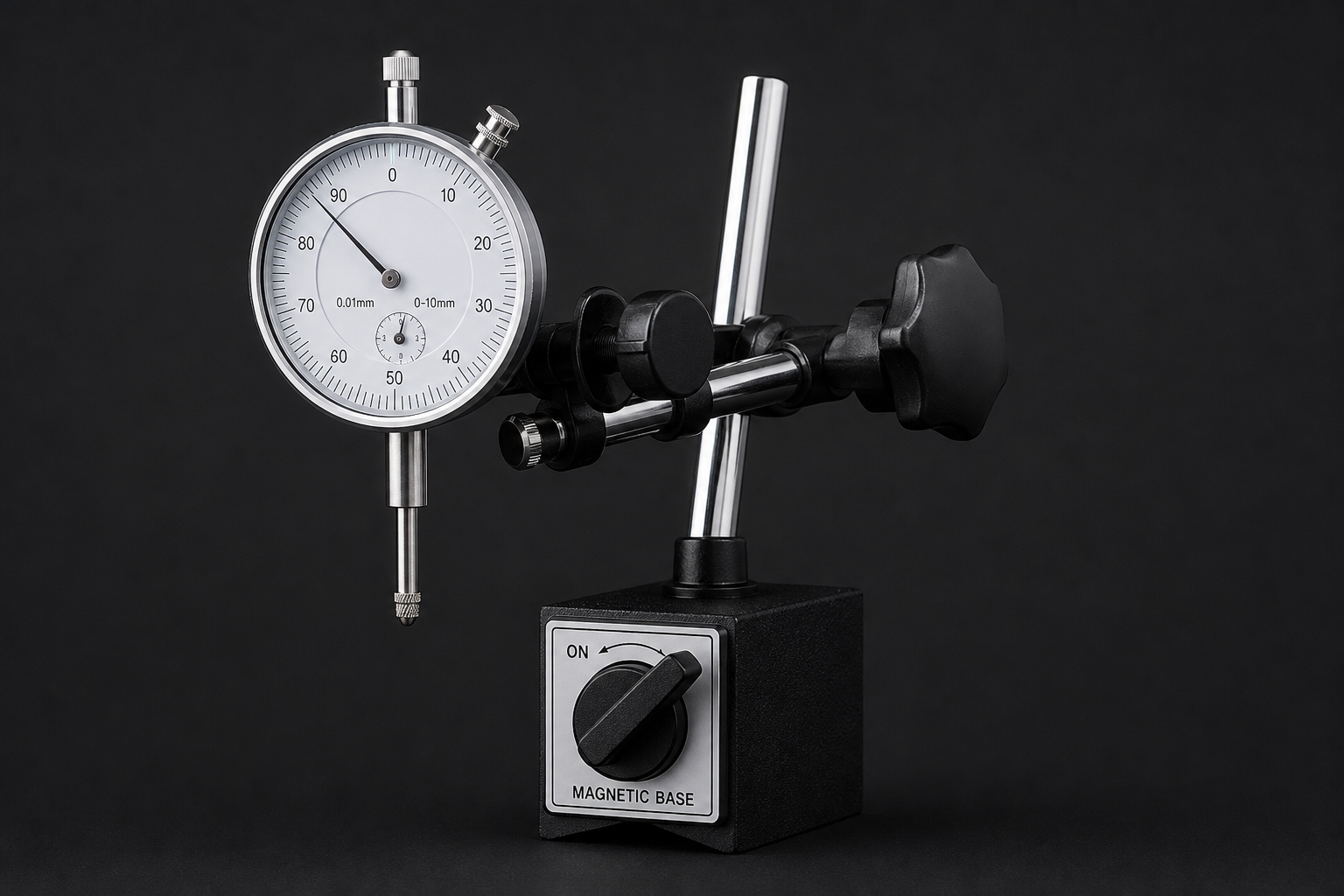
Dial Indicator Set with Magnetic Base
The only honest way to get piston-to-deck at true TDC
Rock the piston through TDC and take the highest reading, not the first
Also finds a block that has already been decked once
As an Amazon Associate, TestTalkHQ earns from qualifying purchases. Prices and availability can change.
What compression ratio actually is
It is a ratio of two volumes, and nothing else. Heywood's Internal Combustion Engine Fundamentals puts it in one line in section 2.2: the compression ratio is the maximum cylinder volume divided by the minimum cylinder volume. The maximum is what sits above the piston at bottom dead centre — the swept volume plus whatever is left at the top. The minimum is that leftover on its own, which is called the clearance volume.
CR = (Vd + Vc) ÷ Vc
Vd = (π ÷ 4) × bore² × stroke (swept volume, one cylinder)
Vc = clearance volume at top dead centre
There is nothing empirical in that. No test, no correlation, no coefficient anybody tuned. Which is exactly why getting it wrong is so avoidable, and why the failures are always in the inputs rather than the arithmetic.
The four things that make up the clearance volume
Heywood's Vc is a single symbol. On a bench it is four separate things, and each one is a part you chose:
That decomposition is HOT ROD's, from How to Calculate Compression Ratio, and it is the form every engine builder works in because those are the four things on the parts list. Change the head and the chamber changes. Change the gasket and the gasket volume changes. Deck the block and the deck volume changes. Order a different piston and the piston volume changes. Nothing else can move the number.
The sign on the piston volume is the single most common mistake. A dish or a set of valve reliefs is extra space above the crown, so it goes in as a positive number and it lowers the compression ratio. A dome fills space, so it goes in negative and raises the ratio. Reverse a 7 cc piston and you will be roughly two compression points out, in the direction that makes the build look safer than it is. If the calculator tells you the clearance volume came out negative, this is why.
Where the errors really come from
Run the sensitivity on any normal V8 and the picture is consistent. A thousandth of an inch of compressed gasket thickness is worth a few hundredths of a compression point. A cubic centimetre of chamber volume is worth about the same. Those are small, buyable increments, and if you are arguing about them your answer is already good enough.
The errors that actually bite are categorical rather than incremental:
The block has been decked and nobody said. Motortopia quotes the case directly: a builder assumes the stock 10.720 in deck height, the block is really at 10.700 because the decks were cleaned up years ago, and a target of 11.9:1 arrives as roughly 12.5:1. Twenty thousandths of missing deck, most of a compression point, and no part on the invoice is wrong.
The chamber is not the catalogue's chamber. Published head specs are for an unmodified casting. New valves, new seats, a skim cut, any pocket work at all, and the number on the page belongs to a different head.
The gasket figure is the wrong one. Composition gaskets crush meaningfully; the bench thickness and the compressed thickness are different numbers and only one of them belongs in the equation.
The piston is not quite the piston on the box. Manufacturing tolerance on a dish or a dome is real, and valve reliefs are often not counted in the headline figure.
Every one of those is found with a burette, a plate and a dial indicator, and none of them is found with a calculator. As EngineBasics puts it: “Unless you have actually measured the engine (CCed the chambers and pistons in the bores), these calculations are estimations, at best. Treat them as such.”
Deck clearance from the block, rather than from a guess
Piston-to-deck clearance is a measurement, taken with a dial indicator on the crown at true top dead centre. But it is also a consequence of four dimensions that are individually easier to check, and working it both ways is how you catch a block that is not what you assumed.
Those are exactly the four dimensions Jon Kaase Racing Engines describe checking against the block deck height — half the stroke, the rod, the compression height and the piston-to-deck dimension. Positive means the crown sits down the bore. Negative means it stands proud of the deck, which is a legitimate build but changes the sign of the deck volume.
Why builders leave a few thou. Motortopia notes that most builders ask for 0.005 or 0.010 in down the bore rather than a true zero deck, specifically so the block can take a skim cut later without the piston hitting the head. A zero deck puts the entire quench distance into the gasket and leaves you nothing in hand.
Quench, and why it is not a separate subject
Quench — or squish, or piston-to-head clearance — is the gap between the flat of the piston crown and the head at top dead centre. Summit Racing's technical article defines it in one line, and it is the same two numbers you already entered:
quench = deck clearance + compressed head gasket thickness
It belongs on a compression ratio page because the two move together and people trade one against the other without noticing. Fitting a thicker gasket to drop compression also opens the quench, and past a point that costs you more detonation margin than the lower ratio bought.
Max RPM
Connecting rod type
Quench range
6,000 or less
Steel
0.035 – 0.045 in
6,000 +
Steel
0.038 – 0.043 in
Any
Aluminium
0.050 – 0.065 in
Table reproduced from Summit Racing technical article SR‑04941, What is engine quench? Aluminium rods get longer as they get hotter, which is why they want the wider gap.
Do not use gasket thickness as a compression control. Summit are explicit: “Don't run more than 0.060 in. quench trying to lower Compression Ratio. This will slow the combustion process and could cause Detonation.” If you need to shed a point of compression, the piston is the right part to change.
The dynamic ratio, and what the cam took back
The static ratio assumes compression starts at bottom dead centre. It does not. It starts when the intake valve seals, and on every performance cam that happens well after bottom dead centre — often sixty or seventy crank degrees after. By then the piston is already a long way back up the bore, and the stroke available to compress is shorter than the crankshaft's.
The geometry is exact and comes straight from Heywood. The distance from the crank axis to the wrist pin at any crank angle is:
s = a cos θ + √( l² − a² sin² θ )
a = stroke ÷ 2 · l = rod length · θ measured from TDC
intake closing at x° ABDC means θ = 180° − x
dynamic stroke = l + a − s (what is left above the piston)
DCR = ( (π÷4) × bore² × dynamic stroke + Vc ) ÷ Vc
The shop-floor version of this calculation, published by EngineBasics under different symbol names, is the same equation — it was checked term by term against Heywood before this page was built, and the two agree to machine precision across every engine and every angle tested.
Seat timing, not 0.050 in timing. This is the input people get wrong, and it is wrong in the flattering direction. EngineBasics: “Since compression cannot start until the intake valve is closed, it is necessary to use seat times when calculating the DCR. Using .050" timing will give an incorrect answer since the cylinder is not sealed. At .050" tappet lift, using 1.5 rockers, the valve is still off the seat .075" and .085" with 1.7 rockers.”
One useful consequence: the bore cancels out of the dynamic ratio entirely. Once you have the static ratio and the dynamic stroke, DCR = 1 + dynamic stroke × (SCR − 1) ÷ stroke. The calculator prints that as a cross-check on its own volume arithmetic.
Why cam makers ask for more compression. A longer-duration cam closes the intake later, which drops the dynamic ratio. Raising the static ratio puts it back. That is the entire reason a catalogue lists a recommended compression ratio next to a camshaft, and it is why a big cam in a stock-compression engine feels soft everywhere below the power band.
What this calculator will not tell you
Four things, deliberately, because there is no honest number for them:
What octane you need. There is no published relation from compression ratio to a required fuel. It depends on chamber shape, quench, cam timing, ignition advance, head material, intake air temperature, coolant temperature, altitude, mixture and knock strategy. The page quotes one author's dynamic-ratio bands with attribution and calls them what they are.
Cranking or cylinder pressure. The relation P = Patm × CRγ exists, but γ is chosen by judgement somewhere between 1.2 and 1.3 depending on the engine, so a printed psi figure would read like a measurement and would not be one.
A typical chamber volume or piston dish for your engine. Marks' Standard Handbook says plainly that clearance volume “is usually measured directly”. Published volumes vary part to part. A representative figure here would be the exact mistake this page exists to prevent.
Your intake closing angle from a cam duration. That needs the lobe, the installed centreline and the lash, and it has to be the seat figure. Read it off the card, or degree the cam.
Frequently asked questions
How do you calculate engine compression ratio?
Divide the cylinder volume at bottom dead centre by the cylinder volume at top dead centre: CR = (swept volume + clearance volume) ÷ clearance volume. Swept volume is (π÷4) × bore² × stroke for one cylinder. Clearance volume is the combustion chamber volume, plus the volume of the head gasket bore, plus the volume between the piston crown and the block deck, plus the piston's dish or valve reliefs, minus its dome.
Does a piston dish add or subtract from compression ratio?
A dish or valve relief adds to the clearance volume and therefore lowers the compression ratio, so it is entered as a positive volume. A dome displaces clearance volume and raises the ratio, so it is entered as a negative volume. Getting the sign backwards on a 7 cc piston shifts the answer by roughly two full compression points.
Do I use the compressed or uncompressed head gasket thickness?
The compressed thickness, which is the published installed figure. Composition gaskets crush noticeably between the bench measurement and the torqued-down thickness; multi-layer steel gaskets move very little. The compressed figure is also the one that goes into the quench calculation.
What is the difference between static and dynamic compression ratio?
Static compression ratio is pure geometry, measured from bottom dead centre, and it is what a spec sheet prints. Dynamic compression ratio measures from the point where the intake valve actually seals, which on any performance cam is well after bottom dead centre, so the effective stroke is shorter and the ratio is lower. The dynamic figure is the one the engine runs on, and it is why a longer cam needs more static compression to feel the same.
Should I use the seat timing or the 0.050 inch timing for dynamic compression ratio?
Seat timing. Compression cannot begin until the cylinder is sealed, and at 0.050 in of tappet lift the valve is still 0.075 in off its seat with 1.5 rockers, or 0.085 in with 1.7 rockers. Using the 0.050 in figure returns a dynamic ratio that is too favourable.
How much does head gasket thickness change compression ratio?
On a typical V8, roughly a few hundredths of a compression point per thousandth of an inch of compressed thickness — enough that the step from a 0.039 in gasket to a 0.051 in one is a real change you can plan around. Remember it moves quench by exactly the same amount, in the same direction.
What is quench and how is it calculated?
Quench, also called squish or piston-to-head clearance, is the gap between the piston crown and the head at top dead centre. Summit Racing's technical article gives it as deck clearance plus compressed head gasket thickness, and recommends 0.035–0.045 in for steel rods up to 6,000 rpm, 0.038–0.043 in above that, and 0.050–0.065 in for aluminium rods.
Does decking the block raise compression ratio?
Yes. Removing material from the block deck reduces the deck height, which brings the piston closer to the deck at top dead centre, which shrinks the deck volume and therefore the clearance volume. Twenty thousandths of an inch is worth most of a compression point on a typical engine, which is why an unverified deck height on a rebuilt block is one of the commonest ways for a calculated ratio to come out wrong.
Does compression ratio depend on the number of cylinders?
No. Compression ratio is a per-cylinder figure. Cylinder count only affects total displacement, which is why the calculator reports displacement separately and does not let it touch the ratio.