A cylinder rod in compression does not fail the way it fails in tension. Where the equation comes from, what the manufacturers publish, how to choose a safety factor from three sources that disagree, where Euler stops being true, and how to work backwards to the smallest rod and the longest stroke that will do the job.
Two failure modes, one rod
Take a length of 5/8 in cylinder rod and pull on it. It will carry thousands of pounds before anything happens, because you are working the steel against its tensile strength and that is a large number. Now push on the same rod with the same force, with two feet of it hanging in free air between the gland and whatever it is pushing. It bows, and then it folds.
Nothing about the steel changed. What changed is the failure mode. In tension a rod fails when the stress reaches the strength of the material. In compression a long rod never gets that far — it goes sideways first, at a load that has nothing to do with how strong the steel is.
That distinction is the whole subject. It also explains the single most common wrong instinct in the shop: specifying a harder, higher-grade rod to cure a bending problem. It does not work, and the reason is in the equation.
Euler’s number, and what is not in it
A column in compression is stable only while it is perfectly straight and perfectly loaded through its own axis. It never is. There is always a thousandth of bow in the rod, a thousandth of clearance in the clevis pin, a fraction of a degree of tilt in the mounting face. Below a certain load those imperfections stay small, because the stiffness of the rod straightens it faster than the load pushes it sideways. Above that load the balance tips and the deflection runs away in an instant. Leonhard Euler wrote the tipping point down in 1757 and it has not needed revising:
Read what is in there, and more importantly what is not. There is a diameter, raised to the fourth power. There is a length, squared, in the denominator. There is E, the elastic modulus — a measure of stiffness, of how much a material springs back. And there is K, which describes how the two ends are held.
There is no strength term at all. No yield strength, no tensile strength, no hardness.
That fourth power also means the measurement matters. Read the rod diameter off the catalogue and you are probably fine; read it off a worn, re-plated rod with a micrometer and you may find two per cent less than you expected, which is eight per cent off the answer.
What the cylinder manufacturers publish
This is not something the trade has to derive. Festo prints it in its technical information for pneumatic cylinders, under a buckling load graph plotting piston rod diameter against stroke length and force:
l = buckling length = 2 × stroke length · S = safety factor (selected value: 5)
Hänchen publishes the same equation for hydraulic cylinders, with the mounting pulled out into an explicit installation factor x, an elastic modulus of 210,000 N/mm², and a safety factor quoted as 3 to 5. Bosch Rexroth works the same ground from the stress side, and states its margin in plain words: “the recommendation of safety against buckling of 3,5 given in the catalogue is a figure based on experience that has proven successful in the industrial use of cylinders… the selected safety factor should not be less than 2,5.”
Festo’s “buckling length = 2 × stroke” is not a competing theory. It is the worst mounting case — a rigidly held cylinder body with nothing at all restraining the rod end — folded into the length instead of carried as a separate factor. The two published forms are the same equation.
Check it. For a 14 mm rod, J = π × 14⁴ ÷ 64 = 1,885.7 mm⁴. With E = 210,000 N/mm², l = 2 × 500 = 1,000 mm and S = 5, that gives FK = 781.7 N — short of the 800 N wanted.
For a 16 mm rod, J = 3,217.0 mm⁴ and FK = 1,333.5 N — comfortably over. The exact minimum works out at 14.08 mm, so 16 mm genuinely is the next size that fits.
One example pins down four things at once: the formula, the modulus, the safety factor of 5, and which way round the units go.
Any trade
Contractor Job Estimator
Price remodels and GC work, then send a quote with no internal numbers.
Excel or Google Sheets. Best on a computer.
$29.00
BuyCheckout opens in a new tab.
The gear this argument actually needs
Everything on this page comes down to three measurements and one adjustment: the rod diameter, the free span, whether the rod is still straight, and the pressure you are feeding it. The first two decide the answer, the third settles whether you have a problem at all, and the fourth is the only lever you can pull on an installed cylinder without changing hardware.
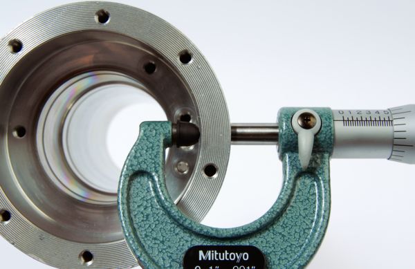
Mitutoyo 103-177 Outside Micrometer 0–1 in
- Buckling capacity goes as the fourth power of rod diameter
- A hard-chromed rod is ground under the plating — the finished size carries the load
- Also measures plating loss and wear on a rod that has been in service
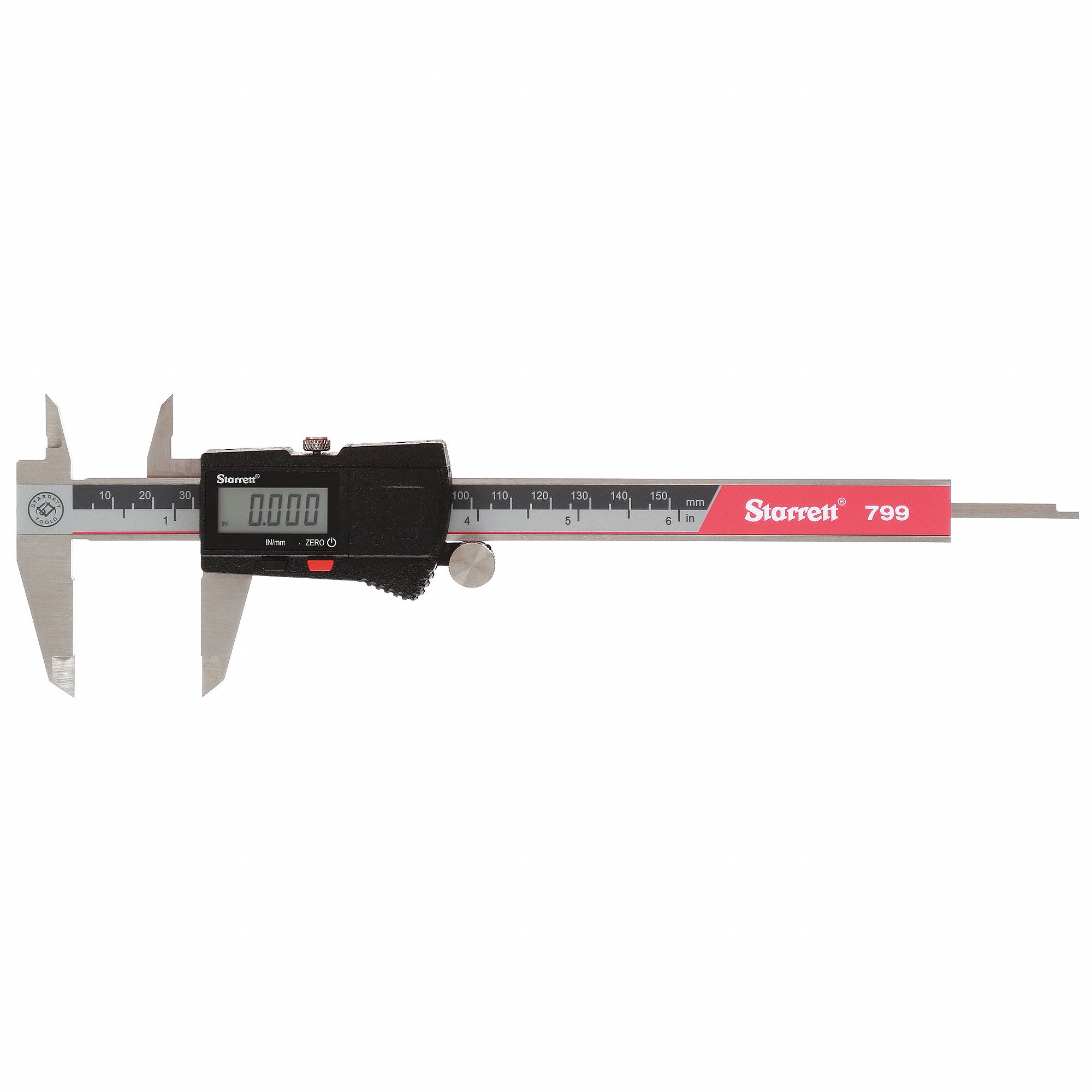
Starrett EC799A Electronic Caliper 0–6 in
- Free span is stroke plus every extension, clevis and coupling nut on the end
- Checks rod, pin bore and clevis in one pass
- Inch and metric together, which is the whole problem on an imported cylinder
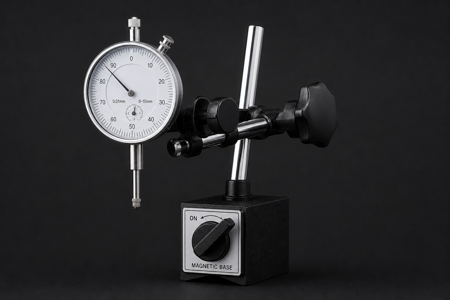
Dial Indicator Set with Magnetic Base
- Runout on an extended rod settles the “is it bent” argument with a number
- Magnetic base clamps to the machine frame, so you read against the real datum
- Finds the difference between a bowed rod and a worn gland

LE LEMATEC Regulator & Flow Control Valve
- Take a third off the pressure and you take a third off the load on the rod
- Flow control also takes the end-of-stroke shock out
- 0–150 psi covers ordinary shop supply
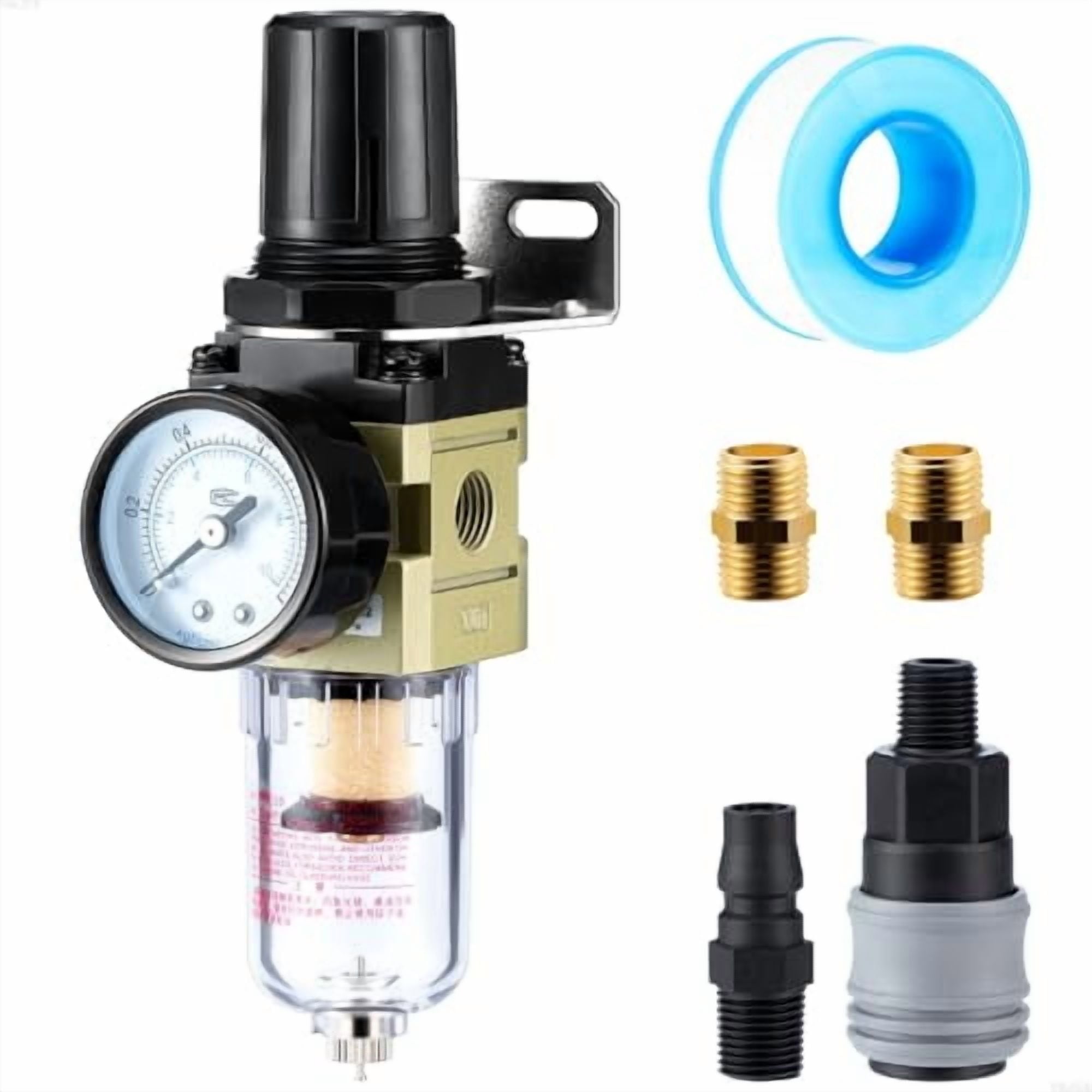
Hromee 1/4 in Filter Regulator AW2000-02
- A regulator at the cylinder is the only way to know what it really sees
- Header pressure with the rod stalled on a stop is the load it must survive
- Filtration keeps the gland and rod surface out of the failure story
As an Amazon Associate, TestTalkHQ earns from qualifying purchases. Prices and availability can change.
What goes in the length box
The length in the equation is the unsupported span between the two supports, with the rod fully extended. Buckling is worst at full extension, which is why that is the only position worth checking.
For a bare rod pushing directly on something, that span is the stroke. This is the convention the manufacturers use and it is what the calculator assumes when the extra-length box is left at zero.
Add to it anything that lengthens the free span:
- A rod extension screwed onto the end
- A long rod eye, clevis or ball joint — the pin centre is the support, not the rod face
- A coupling nut or jam nut stack
- A stub projecting past a guide bush to reach the load
Do not add the cylinder body. The tube is not part of the column; it is one of the supports. A 24 in stroke cylinder is not a 40 in column because the overall envelope is 40 in.
Choosing a safety factor
Three manufacturers, three numbers, and they do not agree. That is not sloppiness; it reflects genuinely different duties.
| Source | Safety factor | Context |
|---|---|---|
| Festo | 5 (their selected value) | Pneumatic cylinders, published graph |
| Hänchen | 3 to 5 | Hydraulic cylinders, simplified Euler method |
| Bosch Rexroth | 3.5 recommended, 2.5 absolute floor | Industrial hydraulic cylinder selection |
The important thing to understand is what that margin is actually paying for. It is not spare load capacity waiting to be spent. Euler’s equation assumes a perfectly straight rod, a perfectly axial load, and perfectly rigid supports. None of those exist. The factor is buying the difference between that clean assumption and a real machine: manufacturing bow in the rod, clearance and wear in the clevis pin, a mounting face that is a degree out of square, a load that is slightly off-centre, and a pressure that occasionally spikes above the regulator setting.
In practice: use 5 for pneumatics unless you have a reason not to. Drop to 3.5 when the installation is genuinely well controlled — a machined mounting, a guided load, a regulated pressure, an axial duty you can describe. Do not drop to 2.5 to make a marginal cylinder pass; that is spending the margin on arithmetic rather than on engineering.
Where Euler stops being true
Euler’s formula has one honest flaw: as the length goes to zero it goes to infinity. Feed it a one inch length of one inch rod and it will cheerfully report millions of pounds. It does not carry that. It squashes.
The standard treatment splits columns by slenderness ratio, λ = K × L ÷ r, where r is the radius of gyration — which for a solid round rod is simply d ÷ 4. Above a transition value the rod buckles elastically and Euler is right. Below it, the steel begins to yield before the elastic buckling load is ever reached, and Euler is optimistic. The transition sits where the Euler stress falls to half the yield strength:
λ < λt → Johnson parabola: Pcr = A × [ Sy − (1÷E) × ( Sy × λ ÷ 2π )² ]
For a chrome-plated rod, λt lands near 116. A 5/8 in rod at 24 in of stroke in the worst mounting case has a slenderness of about 307 — a long way into Euler territory, which is where nearly every real cylinder rod lives.
There is one situation where this matters in practice, and it is not the obvious one. Guiding the load cuts the effective length by a factor of four, which on a short stroke can drop the rod straight under the transition. When that happens the gain from guiding is less than the sixteen-times the mounting table implies — not because the guiding is worth less, but because the rod has run into a different limit. That is the calculation being honest rather than flattering.
Working backwards
Checking a cylinder you already have is the easy direction. The two useful questions are the other way round.
What is the smallest rod that will do this? Fix the load, the length and the mounting, and solve for diameter. The answer will be an awkward number like 14.08 mm or 0.704 in, because rod diameters are not continuous. Take the next standard size up, never the nearest — rounding down here is rounding into the margin you just chose.
How long can I make this stroke? Fix the rod and the load and solve for length. This is the question worth asking before you commit a machine layout, because stroke is usually the cheapest thing to change on a drawing and the most expensive thing to change on a built machine.
Both answers move dramatically with the mounting case, which is why that is worth settling first — see pivot versus rigid cylinder mounting for the argument in full.
The order to size a cylinder in
- Force. What does the job need, and at what pressure will you run? Bore follows from those two. The trade-off between a bigger bore and a higher pressure is argued in full in bigger bore versus higher pressure, and it has consequences well beyond the cylinder.
- Stroke. From the geometry of the machine.
- Mounting. Decide it deliberately, because it is worth a factor of sixteen.
- Rod. Check it against this calculation. If it fails, the levers in order of cost are: guide the load, reduce the pressure, shorten the stroke, go up a rod size, go up a bore size.
- Side load. Separately, from the manufacturer’s published figure.
- Air. What the cylinder costs you per cycle — see the cylinder air consumption calculator — and whether the valve and fittings can feed it, which is the Cv question.
Notice that the rod check comes after the mounting and before the purchase order. That ordering is the whole point: by the time a cylinder is bolted to a machine, four of the five levers have already been spent.
Frequently asked questions
How do you calculate piston rod buckling?
With Euler’s column formula divided by a safety factor: permissible load = π² × E × J ÷ (K × L)² ÷ S, with J = πd⁴÷64 for a solid round rod, E about 210,000 N/mm² for rod steel, L the unsupported length at full extension, K set by the mounting, and S the safety factor. Festo publishes this form for pneumatic cylinders with S = 5 and the buckling length taken as twice the stroke.
Does a stronger rod resist buckling better?
No. Elastic buckling depends on stiffness, not strength, and all steels share essentially the same elastic modulus. A hardened high-tensile rod buckles at the same load as a mild one of the same diameter. Increase the diameter instead — capacity goes as the fourth power of it.
What safety factor should I use?
Festo selects 5 for pneumatic cylinders, Hänchen quotes 3 to 5 for hydraulics, and Bosch Rexroth recommends 3.5 with 2.5 as a stated floor. Use 5 for pneumatics by default; 3.5 when the installation is genuinely well controlled; never below 2.5.
Do I use the stroke or the whole cylinder length?
The unsupported span between supports at full extension. For a bare rod that is the stroke. Add rod extensions, long clevises, coupling nuts and any stub projecting past a guide. Do not add the cylinder body — the tube is a support, not part of the column.
Does buckling matter on the retract stroke?
No. Retracting puts the rod in tension, and a rod in tension cannot buckle. It is purely an extend-stroke problem and it is worst at full extension.
What is a stop tube and do I need one?
A spacer inside the cylinder that keeps the piston from reaching the very end of the tube, maintaining a minimum distance between piston and rod bearing. That distance is what resists the rod tilting inside the cylinder, so it cuts the leverage a long extended rod applies to the gland. Long strokes are where they are used. There is no general formula for the length — it is published per cylinder series, so ask the manufacturer.
Why does the calculator sometimes say Johnson instead of Euler?
Because the rod is short and fat enough that pure Euler would flatter it. Below a slenderness ratio of roughly 116 for steel, the material starts yielding before the elastic buckling load is reached, and the Johnson parabola is the standard correction. If you see it, buckling is probably not your binding constraint.
Can I just turn the pressure down?
Often, yes, and it is the cheapest fix available on an installed cylinder. Thrust is directly proportional to pressure, so a cylinder regulated to 60 psi instead of 90 carries a third less load on its rod. If the job only needs enough force to close a gate, it does not need header pressure to do it.