
The arithmetic cannot be wrong, so an input is. A diagnostic order for a compression ratio that does not match the engine: the sign on the piston volume, an undisclosed deck cut, a chamber that is no longer the catalogue’s, compressed versus bench gasket thickness, the finished bore, a static ratio that is right while the cam is wrong, and what to look at when the number checks out and it still detonates.
The symptom, and what it is really telling you
Something does not add up. Either the engine you built detonates on the fuel your calculated ratio said would be fine, or it feels flat everywhere and the ratio said it should not, or you cc’d the assembled engine and got a number that does not match the spreadsheet you built it from.
In every one of those cases the arithmetic is not the problem. Compression ratio is the ratio of two volumes — there is no coefficient in it to get wrong and no correlation to misapply. If the answer is wrong, an input is wrong. This is the order to check them in, cheapest and most likely first.
Step 1 — The sign on the piston volume
Check this first because it is the largest single error available and it takes ten seconds.
A dish, or a valve relief, is extra space above the crown. It adds to the clearance volume and therefore lowers the ratio, so it is entered positive. A dome fills space: it subtracts and raises the ratio, so it is entered negative. HOT ROD give the rule in a sentence — “dish volume increases clearance volume, and dome volume reduces clearance volume” — and it is still the most reversed convention in engine building.
The magnitude: on a typical 350-class V8, getting the sign backwards on a 7 cc piston moves the answer by roughly two full compression points, and always in the direction that makes the build look safer than it is. A spreadsheet that says 10.5:1 on a reversed 7 cc dome is describing an engine nearer 12.5:1.
Step 2 — Has the block been decked?
This is the input people assume and should not, and it is the second-largest error on the list.
Block deck height is the distance from the crank centreline to the deck surface. The figure in the manual is the figure the block left the factory at. Any block that has been through a machine shop — and most rebuildable blocks have — may not be at it any more, and nothing about the block’s appearance tells you.
Motortopia put a number on the consequence: a builder assumes 10.720 in, the block is really at 10.700 because the decks were cleaned up at some point, and a target of 11.9:1 turns up as roughly 12.5:1. Twenty thousandths of an inch, most of a compression point, and not one part on the invoice was the wrong part.
Check it two ways and make them agree:
- Measure the deck clearance directly. Dial indicator on a magnetic base, zeroed on the deck, swept across the crown, with the crank rocked through top dead centre so you record the highest reading rather than the first.
- Derive it from the stack. piston-to-deck = block deck height − (stroke÷2 + rod length + piston compression height). Those are the four dimensions Jon Kaase Racing Engines check against each other, and if your measured and derived numbers disagree, one of the four specs you were given is wrong.
Any trade

Contractor Job Estimator
$29.00
BuyCheckout opens here — you stay on this page.
The tools that decide whether the number is real
Everything on this page is arithmetic on four measurements. Three of them cannot be looked up in a catalogue with any confidence — the piston-to-deck clearance, the finished bore and the chamber volume of the head actually on your bench — and the fourth, the compressed gasket thickness, is a published figure that people routinely read off the wrong line. These are the tools that turn assumptions into inputs.
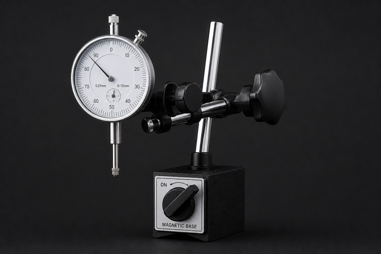
Dial Indicator Set with Magnetic Base
- The only honest way to get piston-to-deck at true TDC
- Rock the piston through TDC and take the highest reading, not the first
- Also finds a block that has already been decked once
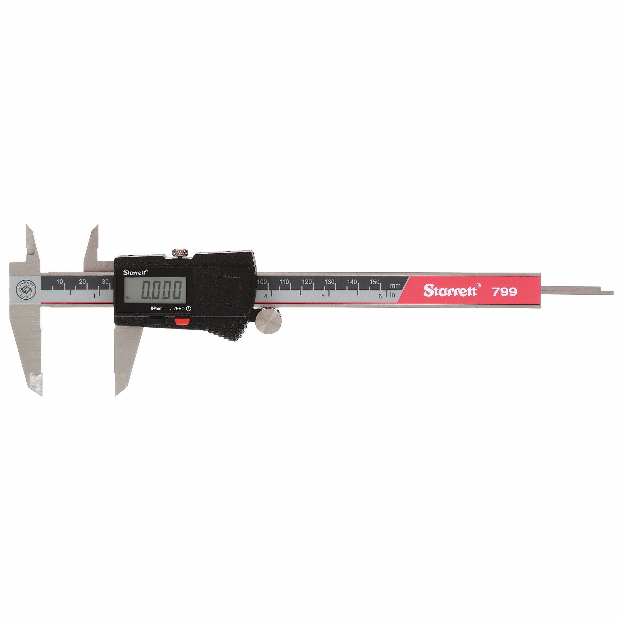
Starrett Electronic Slide Caliper 0–6 in
- Gasket bore, uncompressed thickness and piston compression height
- Enough resolution for the block stack, where tenths of a thou do not matter
- The calculation wants the compressed gasket figure, not this one
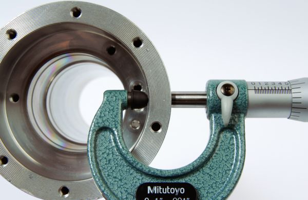
Mitutoyo 103‑177 Outside Micrometer 0–1 in
- Sets the bore gauge that measures the finished cylinder
- Bore enters the swept, deck and gasket volumes at the same time
- A caliper across a bore is a guess; a set micrometer is not
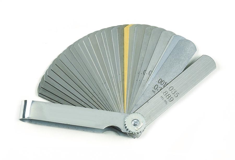
GEARWRENCH 161D 32‑Blade Feeler Gauge Set
- Sanity-checks the 0.035–0.045 in quench band by feel
- Also the tool for the clay check on valve-to-piston clearance
- Cheap insurance against a quench you calculated and never verified
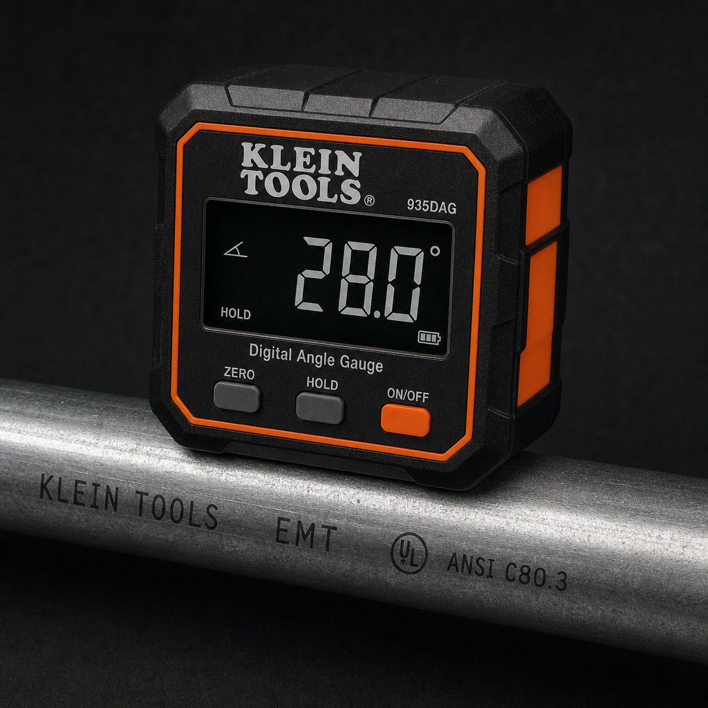
Klein Tools 935DGGP Digital Angle Gauge
- Crank degrees off the damper when a degree wheel is not fitted
- Intake closing angle is the input the dynamic ratio lives or dies on
- Magnetic base sticks to the balancer or the deck
As an Amazon Associate, TestTalkHQ earns from qualifying purchases. Prices and availability can change.
Step 3 — Is the chamber the catalogue’s chamber?
Published cylinder head chamber volumes describe an unmodified casting. Yours may not be one.
New valves sit differently in the seats. A three-angle valve job removes material. A skim cut to true the deck removes more, and takes chamber volume with it. Any pocket work, any unshrouding, any bowl blending — all of it moves the number, and none of it is visible from the part number on the box.
The fix is the one Marks’ Standard Handbook describes for clearance volume in general: measure it. Invert the head, install both valves and a plug, lay a thick acrylic plate with a small hole over the chamber, seal it with grease, and fill from a graduated burette until the last bubble goes. Do every chamber, not one — casting variation between chambers on the same head is real, and so is the variation in anybody’s valve job.
Step 4 — Compressed gasket thickness, not bench thickness
The calculation wants the thickness of the gasket after the head is torqued down. Composition gaskets crush noticeably between those two states; multi-layer steel gaskets barely move.
Two ways this goes wrong. The first is simply reading the wrong line on a catalogue page that lists both. The second is subtler: a gasket that is not torqued to spec will not be at its compressed thickness either, which is one of several reasons head bolt procedure matters here. That side of it — clamp load, torque-to-yield versus conventional bolts, and why a re-used stretch bolt does not deliver the same clamp — is covered in the bolt torque guide and bolt torque vs torque-to-yield rather than repeated here.
Also check the gasket bore. The gasket slug uses the diameter of the hole in the gasket, which is normally larger than the cylinder bore. Using the cylinder bore for both the deck slug and the gasket slug is a small error, but it is free to avoid.
Step 5 — The bore is not the nominal size
A rebuilt block is bored to whatever the wear and the available piston sizes dictated. An 0.030 in overbore is routine, and 0.040 or 0.060 are not unusual on an older block on its second or third life.
Measure the finished bore with a bore gauge set from a micrometer, not with a caliper across the hole. Then use that figure everywhere the bore appears — the swept volume and the deck volume both scale with it.
Step 6 — The static ratio is right and the engine is still flat
If every input checks out and the engine simply has no low-end, you are probably looking at the wrong ratio entirely.
Compression does not start at bottom dead centre. It starts when the intake valve seals, which on a long-duration cam can be seventy crank degrees after bottom dead centre. By then the piston is well back up the bore, and the stroke actually available to compress is a good deal shorter than the crankshaft’s. That is the dynamic compression ratio, and a big cam in a stock-compression engine can pull it down below anything that makes usable torque.
This is the entire reason camshaft catalogues specify a minimum compression ratio next to a grind. The full treatment, including the geometry and the seat-timing trap, is in static vs dynamic compression ratio.
Step 7 — The ratio is right and it still detonates
At this point the number is not the problem and the build is. In rough order of how often it is the answer:
- Quench. Deck clearance plus compressed gasket thickness, per Summit Racing’s technical article. Their bands are 0.035–0.045 in for steel rods to 6,000 rpm, 0.038–0.043 in above that, and 0.050–0.065 in for aluminium rods. A wide quench slows the burn and costs you detonation margin at any given ratio — which is why two engines at the same compression ratio behave entirely differently. Summit are explicit that going past 0.060 in to drop compression is counterproductive: it “will slow the combustion process and could cause Detonation.”
- Heat. EngineBasics: running near the top of the usable range “requires that the engine be well built, with the correct quench distance, and kept cool (170°). Hot intake air and hot coolant are an inducement to detonation.” Coolant concentration is part of that, and the trade-off between freeze protection and heat transfer is covered in the coolant mix ratio calculator and its troubleshooting guide.
- Ignition advance. Outside the scope of any volume calculation, and the first thing to pull back while you find the real cause.
- Chamber shape and head material. Real effects, widely discussed, and with no published number anyone can put in an equation. Beware any source that offers you one.
The quick version
- Piston volume sign — dish positive, dome negative. Worth two points.
- Block deck height — measured, not assumed. Worth most of a point.
- Chamber volume — cc’d, not catalogued. Worth a point on a milled head.
- Gasket thickness — compressed, not bench. Worth a couple of tenths.
- Finished bore — gauged, not nominal. Worth less than you think.
- Static right, engine flat — it is the cam. Work the dynamic ratio.
- Everything right, still knocking — quench, heat, timing.
And the standing caveat, from EngineBasics, which is the right note to end a troubleshooting article on: “Unless you have actually measured the engine (CCed the chambers and pistons in the bores), these calculations are estimations, at best.” If the ratio you are chasing is anywhere near the limit of the fuel you intend to run, it has to be measured rather than calculated.