
A diagnostic order for an air tool that is fine at rest and useless under load: move the gauge to the tool first, establish real consumption, count the restrictions in the drop leg, find the individual culprit, check whether it has gone sonic, and know when the fault is upstream instead.
The complaint, stated precisely
The tool is fine at rest and hopeless under load. The gauge on the regulator reads 90 psi with the trigger up, and the impact wrench still will not shift a lug nut. Somebody has already turned the regulator up, which helped a bit, and somebody else has already blamed the compressor.
Almost every version of this fault comes down to one sentence: pressure drop only exists while air is moving. A gauge on a dead-ended line reads full supply pressure because nothing is flowing, so nothing is being lost. The instant the trigger goes down, every restriction between the header and the tool begins throwing pressure away in proportion to the square of the flow through it. The gauge that read 90 does not read 90 any more — and if it is upstream of the restriction, it will happily go on telling you it does.
Step 1 — Establish what the tool actually wants
You cannot diagnose a flow problem without a flow figure. Take the tool’s rated air consumption from its own data plate or manual, at the pressure it is rated at. Two traps:
- Average versus peak. Some tools are quoted at an assumed duty cycle, which is useless here. The drop happens while the trigger is down, so you need the running consumption, not a 25% average. Where a manual quotes both, use the larger.
- The rating pressure. A tool rated at 90 psig and run at 120 consumes considerably more than its plate figure.
If the plate is missing or illegible, the per-tool CFM requirement calculator and the CFM chart give representative figures by tool type. And if the unit on the plate is not SCFM, read SCFM vs ACFM vs ICFM before comparing it with anything else — those are not interchangeable numbers.
Step 2 — Count the restrictions, not the fittings
Walk the path from the header to the tool and write down everything the air goes through. A typical drop leg is worse than people remember:
- Filter
- Regulator
- Lubricator, if fitted
- Coupler body on the FRL outlet
- Plug on the hose
- Coupler at the tool end of the hose
- Plug on the tool
- Any reducing bushings or street elbows tying those together
That is seven or eight restrictions in series, and each of n equal components has to be √n times the Cv a single component would need. Eight equal restrictions each have to be 2.83× the assembly requirement. This is normally where the fault is, and it is normally the accumulation rather than one villain.
Any trade

Contractor Job Estimator
Price remodels and GC work, then send a quote with no internal numbers.
Excel or Google Sheets. Best on a computer.
$29.00
BuyCheckout opens in a new tab.
The hardware this argument is about
Every number on this page ends up as a decision about four cheap parts: the coupler, the plug that goes into it, the regulator and the filter. They are the restrictions, they are the things you can actually change, and they are almost always bought on thread size rather than on published flow. The hose behind them decides whether any of it survives.
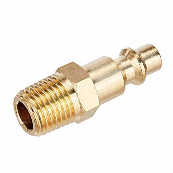
Amazon Basics Quick Connect Coupler & Plug Kit
- A coupler and its plug are two restrictions in series, not one
- Matched sets stop the mixed-profile fits that leak and strangle
- 14 pieces means the whole shop can run one consistent profile

LE LEMATEC Regulator & Flow Control Valve
- A gauge at the tool is how you catch a drop that only exists under flow
- 0–150 psi span covers ordinary shop supply pressures
- Set pressure at the tool, not at the tank, and the argument settles itself
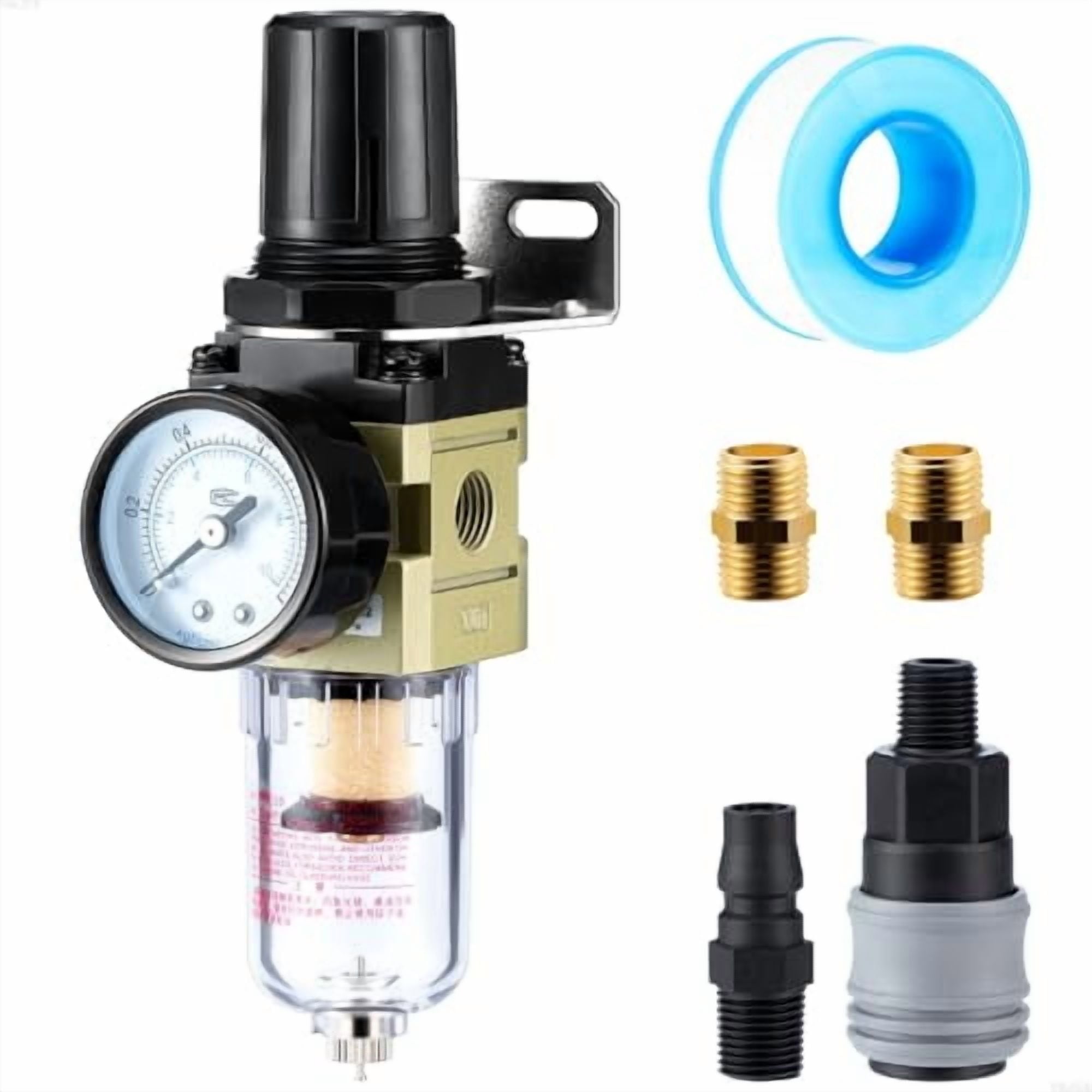
Hromee 1/4 in Filter Regulator AW2000-02
- Combines two of the series restrictions into one body
- A loading element raises the drop over time — the datasheet figure is the clean one
- Bowl drain keeps the element from becoming the restriction
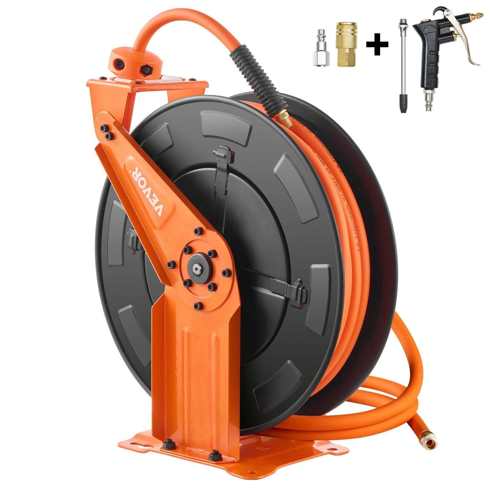
Relhost Retractable Air Hose Reel 3/8 in × 65 ft
- 3/8 in bore instead of 1/4 in is the cheapest flow upgrade on most lines
- Hose loss is friction over a length — a different calculation from Cv
- Right couplers behind an undersized hose just relocate the problem
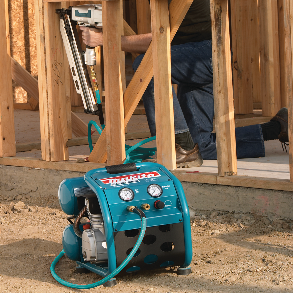
Makita MAC2400 Big Bore Air Compressor
- If supply pressure sags under load, no component choice fixes it
- Published delivered CFM at 90 psi is the comparable number, not horsepower
- Supply first, then components, then hose — in that order
As an Amazon Associate, TestTalkHQ earns from qualifying purchases. Prices and availability can change.
Step 3 — Find the one that is doing the damage
With the tool running under load, measure pressure immediately upstream and immediately downstream of each suspect component in turn. The drop across each one, at a known flow, is a direct measurement of its effective Cv. Work from the tool backwards; the last restrictions in the chain are the most likely and the easiest to get at.
Common findings, roughly in order of how often they turn out to be the answer:
- A small-bore coupler on a big tool. The single most common cause. Automotive-profile couplers in particular are not designed for the flow a 1/2 in impact wrench wants, and they are physically interchangeable with high-flow bodies, so they get fitted by accident constantly.
- Mismatched coupler and plug profiles. Some combinations will click together and hold pressure while sitting much further into the body than intended, throttling badly. If it feels like it engages differently from the others in the shop, suspect it.
- A loaded filter element. Datasheet Cv is a clean-element figure. An element that has been in service for a year without anyone looking at the differential indicator can cost several psi on its own.
- An undersized regulator. Regulators are chosen by port thread far more often than by flow, and a small regulator also droops under flow: its outlet pressure falls below its setting as demand rises, independently of ordinary pressure drop.
- Reducing bushings. A 3/8 to 1/4 bushing in front of a good coupler wastes the coupler.
Run the measured flow and the measured drop through the Cv calculator in reverse — enter the flow, the upstream pressure and the drop you measured, and the required-Cv answer is what that component would have had to be to keep the drop you wanted. Compare that with the datasheet figure for what is actually fitted and the size of the mismatch becomes a number.
Step 4 — Check whether it has gone sonic
If the pressure downstream of a component has fallen to half its absolute upstream pressure, the flow through it is choked and the component is at its absolute ceiling. On 90 psig supply that means an outlet around 38 psig. Past that point the tool cannot get more air out of that component no matter what happens downstream, and the tool is being starved outright rather than merely underfed.
Step 5 — Rule out the hose
Hose is not a Cv problem; it is friction over a length, and it behaves differently. Two checks worth doing before spending money on fittings:
- Bore. 1/4 in hose is extremely common and is the wrong size for anything hungry. Going to 3/8 in is usually the single cheapest improvement available on a shop air line.
- Length. Loss is proportional to length, so a 100 ft reel fully wound out costs several times what the first 25 ft costs. Reels are frequently left fully extended for convenience.
Size hose and pipe with the compressed air pipe size calculator. Fitting a Cv 2 coupler behind fifty feet of coiled 1/4 in hose relocates the bottleneck rather than removing it.
Step 6 — If the tool inlet holds pressure, the fault is upstream
If the gauge at the tool stays close to supply pressure with the trigger down and the tool is still weak, nothing in the drop leg is restricting anything. At that point the problem is one of three things, and none of them is a component Cv:
- The header itself is sagging under load — a distribution or supply problem. That is a different diagnostic path entirely, and we have written it up separately in compressed air pressure drop troubleshooting; there is no point repeating it here.
- The compressor cannot keep up. Compare its published delivered CFM at 90 psi — not its horsepower, and not its tank size — against the tool demand. Leaks eat into that figure continuously; the leak calculator puts a number on how much. At altitude, derate the compressor’s output before comparing anything, using the altitude derate calculator.
- The tool is worn or dry. A motor with worn vanes or a rotor that has never seen oil will consume its rated air and deliver very little torque. Pressure and flow can both be perfect while the tool is simply finished.