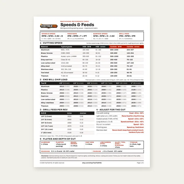
Machining Speeds & Feeds Card
One page. Speeds, chip load and drill feed, imperial and metric.
$3.99
BuyWhen the calculator said the fit was fine — but covers bind, pins won't start, or gaps open on the wrong side
Use this when the Tolerance Stack-Up Calculator (worst-case or RSS) looked acceptable and the assembly still fails in the shop. Method choice and when to prefer worst-case vs RSS are already covered in the Tolerance Stack-Up Guide — this page stays on diagnosis after the math.

Most "the stack passed but the parts don't fit" surprises come from wrong signs in the chain, measuring the wrong features, treating weld distortion like a print ±, mixing inch/mm, or applying RSS on a process that is not centered.
| Symptom | What it usually means | First fix | Next tool |
|---|---|---|---|
| Calc gap OK, covers bind / pins won't start | Wrong direction signs or missing link in the chain | Redraw chain with +/− contribution to the critical gap | Stack-Up Calculator |
| Print WC fails, shop parts usually fit | You used worst-case where selective/RSS production is intended | Confirm method on the drawing note; don't "fix" by ignoring outliers | Stack-Up Guide |
| Weldments never match flat-pattern stack | Distortion treated as print tolerance | Measure after weld; machine critical faces in one setup | Bending Guide |
| Flange / hole pattern drifts after brake | Bend deduction / springback not in the chain | Add formed-length variation; re-check BD | Bend Deduction |
| Inspection fights the print | Wrong datum / feature measured, or unit mix | Same datums as the stack; confirm inch vs mm | Caliper / indicator below |
What it looks like: Worst-case and RSS both look safe in the calculator. On the bench the cover hits the tube, the pin is short, or the clearance opens on the opposite side of the assembly from what you expected.
Likely causes: Each dimension must contribute + or − to the critical result. A "plus" on plate A can close a gap the same way a "minus" on spacer B does. Flipping one sign turns a real interference into a fake clearance (or the reverse).
Fixes: Sketch the chain once with arrows toward "more clearance" vs "more interference." Enter the same signs in the calculator. Re-run only after signs match the sketch — not after changing tolerances hoping the number improves.
What it looks like: Parts fail fit check, but every individual dimension on the CMM or caliper is "in print." The stack used hole center-to-edge; inspection measured edge-to-edge of the plate. Or the stack assumed a machined face while production checked the as-welded face.
Likely causes: Stack chains are feature-specific. Measuring a related but different feature validates the wrong model. Datum shifts (inspecting from the opposite face) add a hidden thickness into — or out of — the chain.
Fixes: Write the stack as "feature A to feature B along this path." Measure those exact features with the same datums. If production cannot reach the drawing datum, change the drawing or the manufacturing sequence — do not invent a parallel stack that only exists at the bench.
What it looks like: Flat laser parts stack cleanly on paper. After welding the frame, covers bind, hole patterns walk, and flush conditions open. Re-running the same ± from the flat pattern still "passes."
Likely causes: Distortion is process capability, not a Gaussian print tolerance. Worst-case and RSS both assume the listed ± bounds the real variation. Weld pull often exceeds that and is biased (not centered).
Fixes: Measure critical interfaces after weld. Prefer weld-rough / machine-critical in one setup. Shorten the stack by creating datums on machined faces. Guide reminder: welded frames usually want worst-case or measure-after-weld — see when each method applies.
What it looks like: Brake-formed brackets or boxes: flange lengths look fine individually, but the assembled envelope is short/long. Hole-to-bend dimensions drift lot to lot.
Likely causes: Stack used flat blank dimensions or nominal flange lengths without the bend deduction / springback variation that actually sets the formed length. Related: wrong K-factor or BD in the flat pattern.
Fixes: Put the formed feature that controls the fit into the stack (flange length after bend, not blank). Calibrate BD with the Bend Deduction Calculator and process notes in the Sheet Metal Bending Guide. Then re-enter the realistic ± for that formed length.
What it looks like: Statistical stack shows a comfortable band. A small percentage of assemblies still hard-interfere, or a safety cover / sealed joint occasionally fails. Or RSS was copied from a high-volume note onto a one-off weldment.
Likely causes: RSS assumes independent, centered, capable dimensions. It does not guarantee every unit. Hard no-go fits, seals, and fixtures need worst-case (or selective fit with documented criteria). Biased processes (torch cut, weld pull) violate the RSS model.
Fixes: Match the drawing method to the risk. If every unit must assemble without selective fit, switch to worst-case in the calculator and on the print note. Method fork detail stays in the guide — do not mix WC and RSS inside one undocumented chain.
What it looks like: Stack totals look absurd (gap of 25" or 0.025 mm when you meant the other). Or inspection rejects parts that "feel" fine because the print called six decimals on a brake flange.
Likely causes: One dimension entered in mm while the rest are inches. Or print precision exceeds process capability, creating inspection fights without improving fit.
Fixes: Convert everything to one unit before entry. Match decimal places to the process (and the guide FAQ). If capability is ±0.030", calling ±0.005" only guarantees scrap — shorten the stack or change the process instead.
Article 3 SKIPPED: Worst-case vs RSS decision forks, shop situations, and tightening levers without over-tolerancing already live in the Tolerance Stack-Up Guide. No separate decision page.
Chart SKIPPED: Side-by-side worst-case vs RSS output is already on the calculator; the guide preference table covers method selection. No unique 400+ word chart data set beyond those pages.
One page. Speeds, chip load and drill feed, imperial and metric.
$3.99
Buy
27 pages. Milling, drilling, tapping, turning and CNC routing.
$12.99
Buy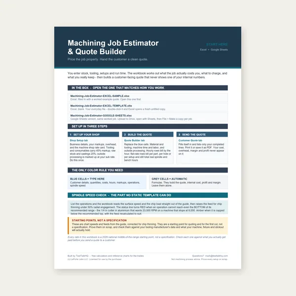
Quote shop work and check operations against your spindle's top speed.
Excel or Google Sheets. Best on a computer.
$29.00
Buy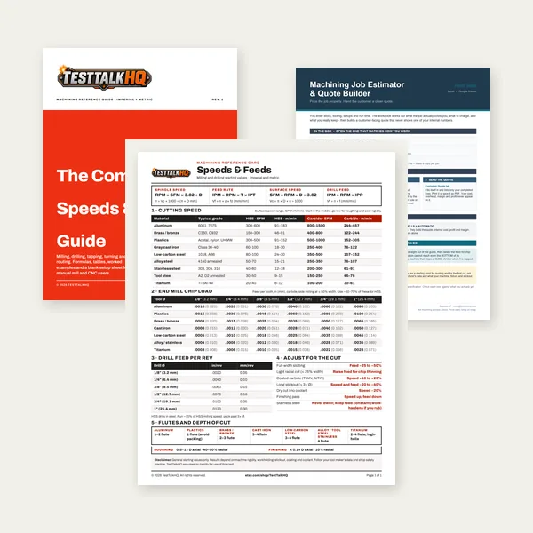
Card, 27-page guide and the estimator workbook. All six files.
Excel or Google Sheets. Best on a computer.
$34.99
$45.98 if bought separately — save $10.99
BuyCheckout opens in a new tab.
Five CSV catalog picks with verified Product Image URLs — measure the same features the chain uses.
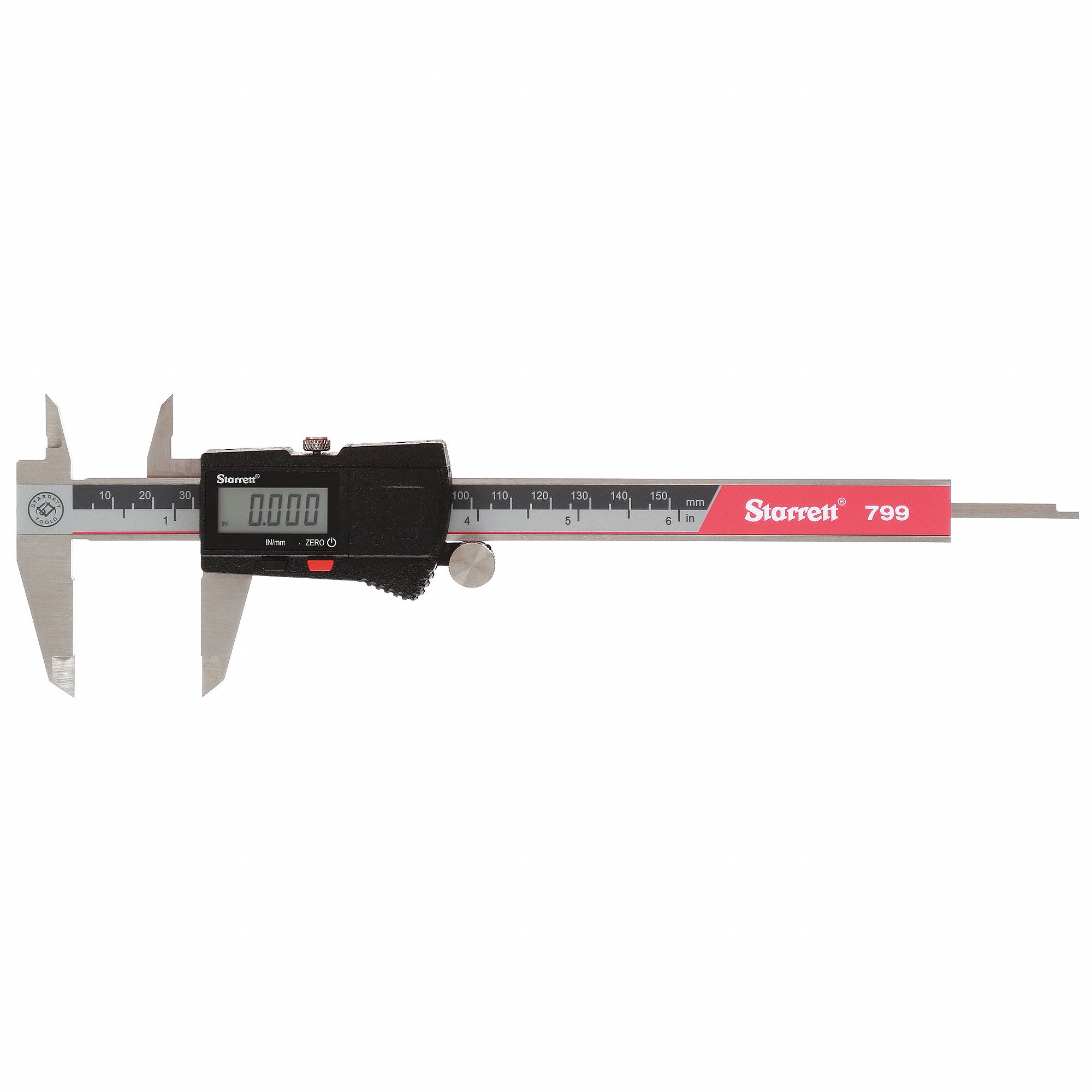
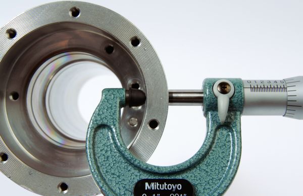
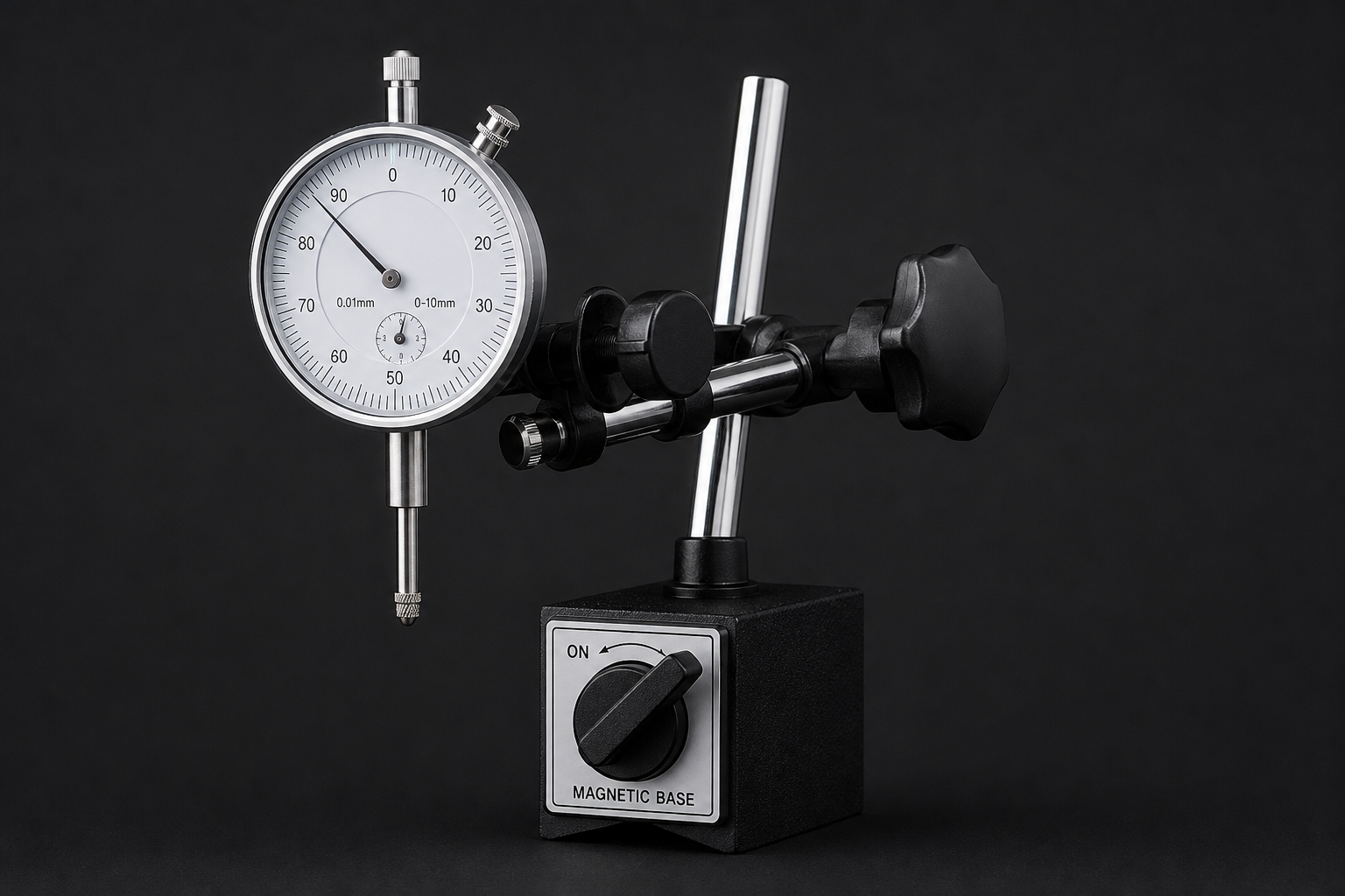
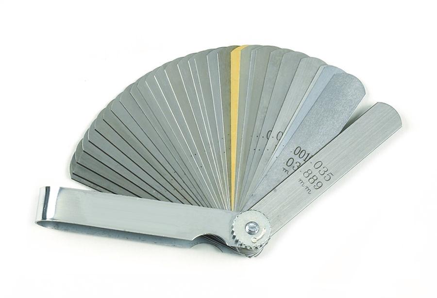
As an Amazon Associate, TestTalkHQ earns from qualifying purchases.
Passing means the model you entered is consistent with itself. Wrong signs, wrong features, missing weld/bend variation, or the wrong risk method (RSS vs worst-case) still produce a clean number. Diagnose the chain, then re-run.
Usually no. Shorten the stack, move precision to a machined setup, or add free clearance (slots/shims). Blind ±0.002 everywhere raises cost without fixing a sign or datum error.
No — that is a different problem set. Tube and sheet forming can feed stack chains; EMT diagnosis lives on Conduit Bending Troubleshooting.