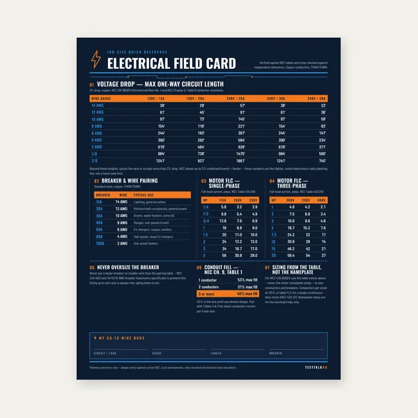
Electrical Reference Card
One page. Voltage drop lengths, breaker and wire pairing, motor FLC.
$3.99
BuyEverything electricians need to size motor branch circuits from nameplate to panel — conductors, OCPDs, overload relays, disconnects, and feeders per NEC Article 430.
Motor circuits are not general-purpose branch circuits. Locked-rotor inrush, Table 430.52 OCPD maximums, nameplate-based overload settings, and separate disconnect requirements all follow Article 430 — not Article 210.
Use the Motor Circuit Sizing Calculator for instant conductor, breaker, and overload sizing, or work through the full guide below.

The National Electrical Code dedicates Article 430 — all 65+ sections of it — specifically to motors, motor circuits, and motor controllers. This is not redundant with Articles 210 and 215, which govern branch circuits and feeders for general loads. The reason for the separate article comes down to one fundamental difference between a motor and every other electrical load: a motor is not a resistive load that draws constant current at full capacity. A motor draws locked-rotor current (LRC) — typically six to eight times its full-load ampere (FLA) rating — for several seconds every time it starts, then settles to its FLA once it reaches running speed.
If you sized motor overcurrent protection the same way you size a receptacle circuit breaker — at 125% of the connected load's full-load current — the breaker would trip on every motor start. The locked-rotor inrush would push current to six or eight times FLA within the first half-cycle, well above any breaker set at 125% FLA. The motor would never reach running speed. The solution is not to eliminate overcurrent protection — it is to separate two functions that Article 210 handles with a single device into two distinct, separately sized protective functions: short circuit and ground fault protection (handled by the branch circuit OCPD per NEC 430.52) and overload protection (handled by the overload relay per NEC 430.32). Each device is sized for a specific threat, and each is permitted to be sized differently from what general-purpose circuit rules would require.
This separation — OCPD large enough to pass starting inrush, overload device small enough to trip on sustained overheating — is the structural logic of Article 430. Every sizing rule in the article exists to honor that distinction. Once you understand why the split exists, the specific percentages in Table 430.52 and Section 430.32 are no longer arbitrary numbers to memorize: they are direct consequences of motor physics.
Before sizing any motor circuit component, you must know which FLA value to use. NEC 430.6(A) is explicit on this point: for the purpose of determining conductor sizes, branch circuit OCPD ratings, and disconnecting means ratings, you use the full-load current values from NEC Tables 430.247 (DC motors), 430.248 (single-phase AC motors), or 430.250 (three-phase AC motors) — not the motor nameplate current. The nameplate current is used only for overload device sizing.
This distinction matters because nameplate current can be higher or lower than the table value depending on the motor's efficiency rating, design class, and the specific manufacturer. The NEC table values represent a conservative upper bound for design B motors that ensures conductor and OCPD sizing is safe regardless of which specific motor is ultimately installed. Nameplate data is more precise and is appropriate for the overload relay, which responds to the actual motor's running current and must be calibrated to protect that specific motor against sustained overheating.
Table 430.250 lists three-phase induction motor FLA values by horsepower and voltage. For motors rated at 480V, use the 460V column values — the NEC provides table values at standard voltage ratings, not system nominal voltages. The 460V column is the correct reference for 480V systems, just as 230V column values apply to 240V systems, and 115V values apply to 120V systems. The most commonly encountered values from Table 430.250 for 460V three-phase motors are: 5 HP = 7.6A, 7.5 HP = 11A, 10 HP = 14A, 15 HP = 21A, 20 HP = 27A, 25 HP = 34A, 30 HP = 40A, 50 HP = 65A, and 75 HP = 96A.
NEC 430.22(A) states the fundamental rule: single motor branch circuit conductors must have an ampacity of not less than 125% of the motor's full-load current rating. Using the table FLA per 430.6(A), this calculation establishes the minimum conductor ampacity before any derating for conduit fill, ambient temperature, or continuous duty.
The 125% factor serves two purposes. First, a motor operating at its full-load nameplate rating is a continuous load — it runs for more than three hours. NEC 210.19(A)(1) requires that branch circuit conductors serving continuous loads be sized at 125% of the load, so 430.22's 125% factor is consistent with that general principle. Second, motors frequently operate near their nameplate rating for extended periods. A conductor sized at exactly 100% FLA would be at its thermal limit continuously, leaving no margin for ambient temperature variation, voltage fluctuation, or periodic overcurrent events. The 25% margin keeps the conductor's operating temperature comfortably below its insulation rating under normal full-load conditions.
Working through the math: a 25 HP, 460V three-phase motor has a table FLA of 34A per NEC Table 430.250. Minimum conductor ampacity: 34A × 1.25 = 42.5A. From NEC Table 310.15(B)(16), 8 AWG THWN-2 in conduit at 75°C has an ampacity of 50A, which exceeds 42.5A. The minimum branch circuit conductor for this motor is 8 AWG THWN-2. If the conduit fill contains four or more current-carrying conductors, or ambient temperature exceeds 86°F (30°C), the 50A ampacity must be derated and the conductor size increased accordingly — but the 125% FLA minimum is the floor, not the ceiling. Both the 430.22 minimum and the derated ampacity must pass; the larger conductor wins.
For wound-rotor motors, NEC 430.22(B) requires conductors to handle 150% of the full-load secondary current. Hermetic refrigeration compressor motors follow NEC 440, not 430.22 directly. Part-winding motors and motors with unusual duty cycles have additional provisions in 430.22(C) through (H). For the vast majority of three-phase induction motor applications in shops and industrial facilities, 430.22(A) at 125% is the applicable rule.
NEC 430.52(C)(1) and Table 430.52 set the maximum rating for the branch circuit short circuit and ground fault protective device. For an inverse time circuit breaker — the most common protective device in commercial and industrial installations — Table 430.52 permits a maximum OCPD rating of 250% of the motor FLA from Table 430.250. This is not a recommendation; it is a maximum. You may use a smaller OCPD if it will hold the starting current without nuisance tripping, but you may not exceed these percentages without invoking the exceptions.
The reason for 250% is motor starting inrush. A Design B squirrel cage induction motor — the NEMA standard for general-purpose motors — draws locked-rotor current of approximately 600% of FLA when first energized. The inverse time characteristic of a standard thermal-magnetic breaker means it will tolerate high current for a short duration without tripping: at 600% of its trip rating, a typical inverse time breaker takes several seconds to trip, which is just long enough for the motor to accelerate to speed and reduce current to FLA. At 250% FLA, the motor's starting inrush of 600% FLA represents only 240% of the breaker's rating — the breaker's time-current characteristic keeps it from tripping during the few seconds of starting.
If the OCPD were sized at 125% FLA as a general circuit breaker would be, the 600% FLA inrush would represent 480% of the breaker's rating — far into the instantaneous trip zone. The breaker would trip on the first half-cycle of every start attempt.
Table 430.52 provides maximum percentages for four common OCPD types when applied to Design B squirrel cage motors (the standard design class for most general-purpose three-phase motors):
Inverse Time Circuit Breaker (standard thermal-magnetic breaker): 250% of motor FLA from Table 430.250. This is the most common selection for commercial and industrial motor circuits.
Dual Element (Time-Delay) Fuse: 175% of motor FLA. Dual element fuses have a time-delay element that tolerates motor inrush without opening, while the non-time-delay element provides fast response to line-to-line faults. The lower percentage relative to an inverse time breaker reflects the fuse's better ability to tolerate starting current at a given rating.
Non-Time-Delay (Fast-Acting) Fuse: 300% of motor FLA. Fast-acting fuses have no intentional time delay; they must be sized higher to allow the starting inrush to pass without opening.
Instantaneous Trip Circuit Breaker (Motor Circuit Protector / MCP): 800% of motor FLA. An MCP has only an instantaneous trip element with no time-delay thermal element. It trips immediately when current exceeds its set point. It can be set at 800% of FLA (or up to 1,300% for Design E motors per NEC 430.52(C)(3)) because at that threshold it provides fault protection only — all overload protection is delegated entirely to the overload relay in the motor controller. MCPs are used exclusively in combination motor controller assemblies where the overload relay is present as part of the assembly; they cannot be used as standalone branch circuit protection because they provide no overload protection by themselves.
NEC 430.52(C)(1) Exception No. 1 permits rounding up to the next standard ampere rating when the calculated percentage does not correspond to a standard OCPD size. A 25 HP motor at 34A FLA with an inverse time breaker: 34 × 2.50 = 85A. Since 85A is not a standard breaker size, Exception No. 1 permits rounding up to 90A — the next standard size in NEC 240.6(A).
Exception No. 2 addresses the situation where even the maximum percentage from Table 430.52 is not sufficient to hold the motor's starting current without nuisance tripping. This occurs with high-inertia loads (large fans, centrifuges, compressors with long acceleration times) or motors with high locked-rotor current code letters. In this case, the OCPD can be increased above the Table 430.52 maximum, but not beyond the absolute ceiling values: 400% for inverse time breakers, 225% for dual element fuses, and 400% for non-time-delay fuses (at 600V or less). These are hard maximums — they cannot be exceeded regardless of starting difficulty.
If a motor's starting requirements cannot be met within these ceilings using a standard fixed-trip OCPD, the solution is not to further increase the OCPD. The solution is to reduce starting inrush through a soft starter, autotransformer starter, or variable frequency drive — all of which limit inrush to approximately 150–300% of FLA during acceleration, making standard OCPD sizing fully sufficient.
Overload protection protects the motor winding insulation from thermal damage caused by sustained overcurrent at levels below the branch circuit OCPD's trip threshold. A motor drawing 140% of FLA for 30 minutes will not trip a 250% FLA-rated breaker — but it will heat the windings to temperatures that degrade insulation over time. Thermal overload protection is specifically designed to detect this condition and de-energize the motor before winding temperature exceeds the insulation class rating.
The overload relay (commonly an electromechanical thermal relay or an electronic overload relay) is installed in the motor controller, in series with the motor circuit. It carries motor current continuously and either directly heats a bimetallic element (thermal relay) or measures current and computes thermal model (electronic relay). When the motor's thermal state exceeds the trip threshold, the overload relay opens the motor controller contacts and removes power from the motor. Unlike the branch circuit OCPD, the overload relay is selected and set specifically for the motor it protects — it is not a generic device sized by HP.
NEC 430.32(A)(1) governs continuous-duty motors rated more than 1 HP. The overload device must be selected at not more than the following percentages of the motor nameplate full-load current rating (not the table value — this is one of the few places in Article 430 where nameplate current is used):
125% of motor nameplate FLA when the motor has a nameplate service factor of 1.15 or greater, or a nameplate temperature rise of 40°C or less. Motors with service factor ≥ 1.15 can sustain moderate overloads continuously without damage — the higher overload trip threshold reflects this tolerance.
115% of motor nameplate FLA for all other motors. Motors without a service factor or with a service factor below 1.15 have less thermal reserve and require a tighter overload threshold.
Service factor (SF) is printed on the motor nameplate. An SF of 1.15 means the motor can continuously deliver 115% of its nameplate HP output without damage — it has built-in thermal margin above rated output. Most standard NEMA B open drip-proof (ODP) and totally enclosed fan-cooled (TEFC) motors have SF ≥ 1.15. Premium efficiency motors and some specialty motors may have SF = 1.00, in which case the 115% overload sizing applies.
Practical example: a 25 HP, 480V motor with a nameplate FLA of 33A and SF of 1.15. Overload trip setting: 33 × 1.25 = 41.25A. Set the overload relay to 41A. If the motor nameplate showed SF = 1.00, the trip setting would be 33 × 1.15 = 37.95A — set at 38A. The difference between these two settings is small, but it matters for motors that run loaded near their nameplate rating continuously.
If the standard overload setting from 430.32(A)(1) causes the overload relay to trip during normal motor operation — not because the motor is actually overloaded, but because of ambient temperature differences, process variability, or slightly high ambient temperature at the controller location — NEC 430.32(C) permits increasing the overload trip setting, but not above 140% of nameplate FLA for motors with SF ≥ 1.15, and not above 130% of nameplate FLA for all other motors. These are absolute maximums. An overload relay set above these values provides insufficient protection against sustained overheating and is a code violation.
If an overload relay cannot be calibrated to hold motor operation without tripping even within these maximums, the cause is not the overload setting — it is an undersized motor, excessive ambient temperature at the motor location, a blocked ventilation path, or a driven load that draws more power than specified. The correct response is to investigate and correct the root cause, not to continue increasing the overload trip threshold.
NEC 430.102(A) requires that a disconnecting means be provided for each motor controller, and that the disconnecting means be located in sight from the controller location. "In sight" means visible from the controller and not more than 50 feet from it. This ensures that a person working on the motor controller can confirm the disconnecting means is open and the circuit is de-energized without walking out of sight of the work area — a basic safety requirement that prevents remote re-energization of a circuit someone is working on.
NEC 430.102(B) adds a separate requirement: a disconnecting means must also be provided in sight from the motor location and driven machinery. Again, within 50 feet and visible from the motor. The intent is identical — a person working on the motor or its driven load can lock out and verify the disconnecting means is open without losing sight of the work location.
In practice, many installations satisfy both 430.102(A) and 430.102(B) with a single disconnect that is within sight of both the controller and the motor. Combination starters with a disconnect in the same enclosure as the controller, mounted adjacent to the motor, satisfy both requirements simultaneously. When the controller is not adjacent to the motor — for example, a centrally located motor control center (MCC) feeding motors throughout a facility — separate disconnects are required at each motor location, even though the controller in the MCC already has its own disconnect.
Exception to 430.102(B): The disconnecting means is not required to be in sight from the motor if the controller disconnecting means is capable of being individually locked in the open position, and if the installation complies with an established lockout/tagout procedure. This exception is commonly used in industrial facilities with MCC-based motor control where it is impractical to install individual disconnects within sight of every motor — provided the facility has a documented and enforced LOTO program and the MCC disconnects are individually lockable.
NEC 430.110(A) sets the minimum ampere rating for the disconnecting means: not less than 115% of the motor's full-load current from Table 430.250. This 115% minimum (as opposed to 125% for conductors) reflects that the disconnect carries current only during running operation, not during the momentary starting inrush — the disconnect is open during normal starts and closes only when the motor is already at running speed in most installations.
For a 25 HP, 460V three-phase motor with a table FLA of 34A: minimum disconnect ampere rating = 34 × 1.15 = 39.1A. A 40A-rated safety switch or circuit breaker used as the disconnect satisfies this requirement.
However, the disconnect ampere rating is not the only specification that matters. Motor circuit disconnects must also be rated for the motor circuit's locked-rotor current, because in some switching sequences the disconnect may open under locked-rotor conditions (a stalled motor, for example). Motor-rated safety switches carry both an HP rating and an ampere rating; the HP rating corresponds to the switch's ability to interrupt locked-rotor current. A 30A general-use switch is not a motor-rated switch and cannot be used as a motor disconnecting means even if its ampere rating exceeds the 115% minimum — it lacks the interrupting rating for motor circuit currents. Use a safety switch or enclosed circuit breaker specifically listed for use as a motor circuit disconnecting means, with an HP rating matching or exceeding the motor's HP at the system voltage.
For a circuit breaker used as the disconnecting means, the breaker's ampere rating and HP rating from its listing both apply. Most standard molded-case circuit breakers (MCCBs) carry a motor HP rating in addition to their interrupt capacity — verify that the breaker's HP rating at the motor's operating voltage is sufficient for the motor it disconnects.
When a single feeder supplies multiple motors, NEC 430.24 governs its minimum ampacity. The rule is: the feeder conductor must have an ampacity not less than 125% of the full-load current rating of the largest motor in the group, plus the sum of the full-load current ratings of all other motors at 100%.
The formula: Feeder ampacity = (FLAlargest × 1.25) + FLAall others
The 125% on the largest motor accounts for the continuous duty rule — the largest motor's contribution to the feeder is treated as a continuous load. The remaining motors are added at their straight FLA because not all motors start simultaneously; in a multi-motor feeder, one motor at a time is typically at its starting inrush, and the starting inrush is handled by the individual branch circuit OCPDs, not the feeder.
Example: a feeder panel feeds a 25 HP motor (34A from Table 430.250), a 10 HP motor (14A), and a 5 HP motor (7.6A), all at 460V three-phase. The 25 HP motor is the largest.
Feeder ampacity = (34 × 1.25) + 14 + 7.6 = 42.5 + 21.6 = 64.1A minimum
From NEC Table 310.15(B)(16), 6 AWG THWN-2 has an ampacity of 65A at 75°C, which satisfies 64.1A. However, if conduit fill, ambient temperature, or both apply derating factors, 6 AWG may fall below the required 64.1A and 4 AWG (85A ampacity) would be required. Always apply all applicable derating factors before confirming the conductor size is adequate.
The feeder OCPD for a motor feeder is sized per NEC 430.62: the feeder protective device shall not exceed the largest branch circuit OCPD rating for any motor in the group, plus the sum of the full-load current ratings of all other motors in the group.
Using the same three-motor example: the 25 HP motor branch circuit has a 90A inverse time breaker (the 250% of 34A = 85A rounded up to next standard size). The other motors' FLAs: 14 + 7.6 = 21.6A.
Maximum feeder OCPD = 90 + 21.6 = 111.6A
NEC 430.62 specifies "not greater than" — the feeder OCPD must not exceed this value. From NEC 240.6(A) standard ratings, 110A is a standard size that does not exceed 111.6A. A 125A feeder breaker would exceed 111.6A and is not permitted. Use a 110A feeder breaker for this example.
The most important conceptual distinction in Article 430 is that short circuit and ground fault protection and overload protection are entirely separate functions, each performed by a different device sized for a different threat. Confusing these two functions — or assuming one device can adequately perform both — is the root of the most common motor circuit design errors.
Short circuit and ground fault protection (the branch circuit OCPD) responds to high-magnitude, short-duration faults: a line-to-line bolted fault, a line-to-ground fault, or a winding insulation failure producing a dead short. These events produce current that is 5 to 20 times the motor's FLA, and the OCPD must clear them quickly — within cycles to a few seconds — to prevent conductor and equipment damage. The OCPD is sized large enough (250% FLA for inverse time breakers) to ride through starting inrush without tripping, but this large size means the OCPD will not respond to a 130% or 150% overload condition that damages the motor gradually over minutes or hours. It is simply rated too high to sense those currents as abnormal.
Overload protection (the overload relay in the motor controller) responds to sustained overcurrent at low multiples of FLA — 115 to 125% for the trip setting, potentially down to 105% if the relay has tight calibration. The overload relay accumulates heat (thermally or by algorithm) and trips after a time delay that mirrors the motor's thermal response to sustained overload. It cannot and does not respond to short circuits — by the time an overload relay would trip on a fault current of 800% FLA, the conductors and windings would already be damaged. The OCPD responds to short circuits before the overload relay can even register them.
Together, the OCPD and overload relay cover the entire threat spectrum: faults are cleared by the OCPD within cycles, overloads are detected and cleared by the overload relay within seconds to minutes depending on the overload magnitude. Remove either device from the circuit and part of the protection spectrum is unguarded. A motor circuit with a correctly sized OCPD but no overload relay has no protection against the gradual overheating that causes most motor failures. A circuit with an overload relay sized at 125% FLA but no OCPD — or an undersized OCPD — has no reliable protection against line-to-line faults that can start fires.
This step-by-step example walks through every component of a complete motor circuit for a 25 HP, 480V three-phase squirrel cage induction motor, Design B, SF 1.15, NEMA TEFC enclosure. Motor nameplate FLA: 33A (a realistic value for this size — always use the actual nameplate value for overload sizing). The circuit runs 75 feet from a 480V motor control center to the motor location in conduit with three current-carrying conductors and no ambient temperature correction required.
Per NEC 430.6(A), use the value from NEC Table 430.250 for all sizing except overload protection. For a 25 HP motor at 460V (the column used for 480V systems): Table FLA = 34A. The nameplate shows 33A, which is slightly lower — the table value is used for conductor sizing, OCPD sizing, disconnect sizing, and feeder sizing. The nameplate 33A is reserved for the overload relay.
Minimum conductor ampacity = 34 × 1.25 = 42.5A
From NEC Table 310.15(B)(16), 8 AWG THWN-2 at 75°C = 50A ampacity. 50A ≥ 42.5A. ✓
Three current-carrying conductors in conduit, no derating factor applies below 4 conductors.
Branch circuit conductors: 8 AWG THWN-2
Inverse time circuit breaker at 250% of table FLA: 34 × 2.50 = 85A. This does not correspond to a standard ampere rating in NEC 240.6(A). Per Exception No. 1, round up to the next standard size.
Branch circuit OCPD: 90A inverse time breaker
Verification: If the 90A breaker causes nuisance trips on starting (unusual for a standard Design B motor of this size), the maximum permitted under Exception No. 2 is 34 × 4.00 = 136A → next standard size is 150A. A 150A inverse time breaker is the absolute maximum permissible for this motor with this OCPD type.
Use nameplate FLA of 33A. Motor has SF = 1.15 → use 125% of nameplate FLA.
Overload trip setting = 33 × 1.25 = 41.25A
Set overload relay to 41A (round down to nearest available setting for conservative protection).
If motor had SF = 1.00 instead: 33 × 1.15 = 37.95A → set at 38A.
Overload relay: set at 41A (125% × 33A nameplate FLA, SF ≥ 1.15)
Minimum disconnect ampere rating = 34 × 1.15 = 39.1A → minimum 40A-rated disconnect.
Select a NEMA-rated safety switch or enclosed breaker with: ampere rating ≥ 40A, HP rating at 480V ≥ 25 HP, and a motor-circuit-rated interrupting capacity.
A standard 30A HP-rated safety switch is inadequate — both because 30A < 40A and because a 30A safety switch is typically HP-rated for motors no larger than 15 HP at 240V. Use a 60A motor-rated safety switch, which meets both the ampere requirement (60A ≥ 40A) and the HP rating (a 60A, 600V-rated safety switch is typically rated for 25–30 HP at 480V).
Disconnecting means: 60A motor-rated safety switch (or equivalent enclosed breaker), within sight of motor and controller
At 75 feet, 8 AWG conductors, 34A full-load current on a 480V three-phase circuit:
VD = (√3 × K × I × L) / CM = (1.732 × 12.9 × 34 × 75) / 16,510 = (1.732 × 32,895) / 16,510 = 56,973 / 16,510 = 3.45V
Percent VD = 3.45 / 480 × 100 = 0.72% — well within the 3% informational guideline at branch circuit level. Voltage drop is not a concern at this run length with 8 AWG on 480V.
| Circuit Component | Calculation | Result / Selection | NEC Reference |
|---|---|---|---|
| Table FLA (design basis) | Table 430.250, 460V column | 34A | 430.6(A) |
| Branch circuit conductors | 34 × 125% = 42.5A min | 8 AWG THWN-2 (50A) | 430.22(A) |
| Branch circuit OCPD | 34 × 250% = 85A → next std size | 90A inverse time breaker | 430.52 / Table 430.52 |
| Overload relay setting | 33A (nameplate) × 125% | 41A (SF ≥ 1.15) | 430.32(A)(1) |
| Disconnect ampere rating | 34 × 115% = 39.1A min | 60A motor-rated safety switch | 430.110(A) |
| Disconnect HP rating | Must equal or exceed motor HP at 480V | Rated ≥ 25 HP @ 460V | 430.110(A) |
| Disconnect location | In sight from controller and motor | Within 50 ft, visible | 430.102(A)(B) |
A combination motor starter integrates several Article 430 required components into a single factory-assembled, listed enclosure. The typical combination starter contains a disconnect (either a fusible disconnect block or a circuit breaker), the motor controller (contactor), and the overload relay — all in one unit. Some configurations also include a control power transformer for 120V control wiring and terminal blocks for field wiring connections.
The disconnect component of a combination starter is typically one of two types. A fusible combination starter uses a fusible disconnect block — a pull-out fuse holder with motor-circuit fuses — as the short circuit and ground fault protection. The fuses are selected per Table 430.52 (175% for dual element fuses, 300% for fast-acting fuses). A circuit breaker combination starter replaces the fusible disconnect with a molded-case circuit breaker sized per Table 430.52, or more commonly a motor circuit protector (MCP) — the instantaneous-trip-only device sized at 800% FLA. When a circuit breaker combination starter uses an MCP, the overload relay must provide all overload protection because the MCP provides only instantaneous fault protection.
Combination starters satisfy multiple NEC requirements simultaneously. The factory listing covers the combination of components as an assembly, which simplifies the field installation and inspection process. The disconnect is positioned to allow a worker to open the circuit before working on the controller or motor — satisfying both 430.102 if the unit is placed within sight of the motor, and the OSHA lockout/tagout requirement for an energy isolation point at the controller.
Combination starters are the dominant configuration in commercial refrigeration, HVAC, pumping systems, and light industrial motor control. They are available in NEMA 1 (open enclosure for indoor clean environments), NEMA 3R (rainproof for outdoor or wet locations), NEMA 4 (watertight), and NEMA 12 (dusttight) enclosures. For facilities with dozens of motors, motor control centers (MCCs) are the MCC equivalent — a lineup of individual combination starter units in a common enclosure, with a main bus feeding all units, significantly reducing field wiring compared to individually mounted starters.
For across-the-line starting of motors up to approximately 100 HP at 480V, a combination starter is the standard and cost-effective solution. For motors requiring reduced-voltage starting (autotransformer starters, part-winding starters, wye-delta starters) or variable speed operation (VFDs), specialty controllers are used — but they still incorporate the same disconnect, overcurrent, and overload protection functions required by Article 430, packaged differently to accommodate the more complex power electronics.
Sizing the branch circuit OCPD at 125% of FLA is the most common motor circuit mistake, typically made by electricians who apply the general continuous load rule (NEC 210.19) to a motor circuit without recognizing that Article 430 supersedes it for this specific component. A 25 HP motor with a 34A table FLA and a breaker set at 125%: 34 × 1.25 = 42.5A → a 45A breaker. When the motor starts, it draws 6 × 34A = 204A for 2–4 seconds. At 204A on a 45A breaker, the breaker is seeing 453% of its rating — deep into the instantaneous trip zone. The breaker trips on every start attempt. The solution is Table 430.52 — 250% for an inverse time breaker, producing a 90A breaker that rides through the inrush without tripping.
NEC 430.6(A) specifies that the table FLA governs conductor and OCPD sizing, but overload protection is specifically excepted — overload devices are sized from the motor nameplate current. Using the 34A table FLA instead of the 33A nameplate FLA on the 25 HP example produces an overload trip setting of 34 × 1.25 = 42.5A instead of the correct 33 × 1.25 = 41.25A. The difference is small in this example, but on a motor where the nameplate current is significantly different from the table value — a premium efficiency motor, a motor on an unusual voltage, or a rewound motor — the error can be meaningful. More importantly, this is a code compliance issue: 430.32(A)(1) explicitly references "nameplate full-load current rating" and using table current violates the section's terms regardless of the numerical impact.
Many installations use the branch circuit breaker as the disconnecting means, which is permitted under NEC 430.102 if the breaker is within sight of the motor and controller (or is lockable in the open position). The problem arises when the breaker's ampere rating is well below the motor's nameplate ratings, which is unusual, but the more common error is the opposite: not verifying that a separately installed safety switch disconnect has an adequate HP rating. A 30A safety switch installed as a disconnect for a 25 HP, 480V motor satisfies 430.110's 115% FLA minimum (39.1A minimum, 30A switch fails this), but even if the wrong-size switch were inadvertently used, a 30A 600V safety switch typically carries an HP rating of only 10–15 HP at 480V — far below the 25 HP motor. The disconnect must meet both the ampere requirement (115% of table FLA) and the HP rating for the motor's actual HP at its operating voltage. Overlooking the HP rating leaves the disconnect unable to interrupt locked-rotor current safely if called upon to open under load.
Combination starter installed at a panel, within sight of the panel — that's not enough. NEC 430.102(B) requires a disconnecting means in sight from the motor location, separate from the controller's disconnect unless the installation complies with the LOTO exception. A motor at the far end of a production floor, 60 feet from its combination starter in the MCC, needs a local disconnect within sight of the motor. Installations that omit this disconnect fail inspection and, more importantly, create a safety hazard: a mechanic working on the motor or its driven equipment cannot verify the circuit is de-energized without walking out of sight of the work area.
General-use AC snap switches (toggle switches) and general-use safety switches are not motor-rated and cannot serve as motor disconnecting means. NEC 430.109(A) requires the disconnecting means to be a listed motor circuit switch rated in HP, a circuit breaker, an isolating switch (for certain conditions), or another listed device specific to motor use. A general-use safety switch lacks the HP rating and the interrupting capacity to break motor locked-rotor current — attempting to open it under load (a stalled motor, for example) will arc the contacts severely and may weld them shut or cause a fire inside the switch enclosure. Motor-rated safety switches carry a clear HP rating on their nameplate and are listed for this duty.
One page. Voltage drop lengths, breaker and wire pairing, motor FLC.
$3.99
Buy
15 pages. Ampacity, corrections, voltage drop, motor circuits, conduit fill.
$12.99
Buy
Quote electrical work and flag panel headroom before you price it.
Excel or Google Sheets. Best on a computer.
$29.00
Buy
Card, 15-page guide and the estimator workbook. All six files.
Excel or Google Sheets. Best on a computer.
$34.99
$45.98 if bought separately — save $10.99
BuyCheckout opens in a new tab.
Measure motor FLA, verify voltage balance, and confirm de-energization before motor circuit work

Measuring motor FLA on all three phases during commissioning requires a true-RMS clamp rated for the motor voltage class. The Klein CL800 reads AC/DC current up to 600A with 1000V CAT IV safety rating — the right meter for verifying phase balance, overload relay settings, and troubleshooting nuisance trips on motor branch circuits.
Check Price
Verifying voltage balance at motor terminals is essential before energizing and when diagnosing overload nuisance trips caused by voltage unbalance. The Fluke 117 reads true RMS voltage with non-contact detection — confirm phase-to-phase readings and de-energization before working at the motor disconnect or controller.
Check Price
High-current measurement on large motor feeders demands a clamp with adequate jaw capacity and true-RMS accuracy on distorted waveforms during motor starts. The Ideal 61-757 handles up to 600A AC/DC — useful for reading feeder current on multi-motor panels and verifying locked-rotor current during commissioning.
Check Price
Quick voltage presence check before working on motor circuits prevents the most avoidable shock incidents at disconnects, MCC buckets, and motor terminal boxes. The Klein NCVT-6 confirms energized conductors without contact before lockout/tagout verification at the motor disconnecting means.
Check Price
Reference breaker for motor circuit OCPD sizing work — NEC Table 430.52 governs maximum branch circuit protection for motors, not the 125% continuous-load rule from Article 210. The Square D QO120 is the industry-standard reference breaker used when comparing general-purpose and motor-circuit OCPD sizing.
Check PriceAs an Amazon Associate, TestTalkHQ earns from qualifying purchases.
Article 430 requires you to use two different full-load ampere values in the same motor circuit calculation — and mixing them up produces either a code violation or a circuit that won't function. For conductors, branch circuit OCPDs, and disconnects, use the FLA from NEC Tables 430.247–430.250, not the motor nameplate. For overload protection only, use the motor's nameplate full-load current. The table values are a standardized design basis that ensures circuit protection is adequate regardless of which specific motor is installed. The nameplate value is used for the overload relay because that device must be calibrated precisely to the individual motor's thermal response — using a generic table value instead of actual nameplate current can result in overload settings that are either too loose (overprotection trip) or too tight (nuisance trips) for the actual motor installed.
The four OCPD types in Table 430.52 — inverse time breaker at 250%, dual element fuse at 175%, non-time-delay fuse at 300%, and MCP at 800% — each carry a different maximum percentage because their time-current characteristics are fundamentally different. A dual element fuse has a built-in time-delay element that absorbs motor starting inrush more efficiently than a thermal-magnetic breaker, so it can be sized lower while still holding starts. A non-time-delay fuse has no delay element and must be sized higher to avoid opening on inrush. A motor circuit protector (MCP) has only an instantaneous magnetic trip with no thermal element at all — it cannot provide overload protection and must be set high enough that only true fault currents trigger it, with the overload relay handling all sustained overload protection. Understanding these characteristics makes Table 430.52 logical rather than arbitrary.
NEC 430.24's feeder sizing rule — 125% of the largest motor's FLA plus 100% of all remaining motors' FLA — accounts for the simultaneous operation of all motors at steady state while applying the continuous duty 125% factor only once, to the motor that contributes the most to the feeder's sustained thermal loading. Only one motor at a time would be at its locked-rotor starting inrush in a typical multi-motor installation, and the individual branch circuit OCPDs absorb that starting current without burdening the feeder. The feeder sees only steady-state running currents from all motors simultaneously, plus a 25% margin on the largest for continuous duty compliance. The corresponding feeder OCPD per NEC 430.62 adds the largest branch circuit OCPD's rating to the other motors' FLAs — not their branch circuit OCPD ratings — keeping the feeder overcurrent protection reasonably tight relative to the feeder conductor ampacity.
A combination motor starter solves a significant field wiring problem: Article 430 requires a disconnect, a controller (contactor), and an overload relay — three separate devices that must be correctly coordinated and installed in compliance with multiple NEC sections. A factory-assembled combination starter provides all three in a single listed enclosure, with the coordination verified by the manufacturer and the UL listing covering the entire assembly. The disconnect is either a fusible block (sized per dual-element fuse rules) or a motor circuit protector (instantaneous trip only, relying on the overload relay for sustained overload protection). Combination starters simplify inspection, reduce field labor, and eliminate the coordination errors that arise when separate components are selected and assembled independently. For the majority of commercial and industrial motor applications below 100 HP at 480V, a NEMA-rated combination starter installed within sight of the motor satisfies essentially all of Article 430's protection and disconnect requirements in one device.
A circuit breaker can serve as the motor disconnecting means under NEC 430.109(A)(1), provided it meets the requirements of 430.110 — including the 115% of FLA ampere rating and an HP rating at the motor's voltage. The critical requirement is location: the breaker must be within sight from both the motor controller location and the motor location per 430.102, meaning visible and within 50 feet. In panel-and-motor installations where the panel is adjacent to the motor and within sight, the branch circuit breaker satisfies both the overcurrent protection function (430.52) and the disconnecting means function (430.102) simultaneously. When the panel is remote from the motor — as in an MCC feeding motors throughout a facility — a separate local disconnect within sight of the motor is required at the motor location in addition to the MCC breaker.
NEC 430.52(C)(1) Exception No. 2 permits increasing the OCPD rating above the Table 430.52 standard values, but only up to hard maximums: 400% of FLA for inverse time breakers, 225% for dual element fuses, and 400% for non-time-delay fuses at 600V or less. If even these maximums are exceeded by the motor's starting requirements, the code does not permit further increases in the OCPD — the solution is to reduce starting inrush rather than to increase the protective device. A solid-state soft starter limits inrush to approximately 200–350% of FLA during acceleration, making standard Table 430.52 percentages fully sufficient. A variable frequency drive limits inrush to approximately 100–150% of FLA — the motor starts with essentially no inrush surge at all, and even the smallest permissible OCPD will hold starts without nuisance tripping.
An overload relay tripping on a properly loaded motor is almost always caused by one of four conditions: the relay is set too low (trip setting below 115% of nameplate FLA for SF < 1.15 motors, or the relay heater elements are selected for a different motor size), the motor is drawing more current than expected due to supply voltage imbalance or low voltage (voltage unbalance above 1% causes disproportionate current unbalance in three-phase motors, increasing the average phase current), the ambient temperature at the controller location is significantly higher than at the motor (thermal overload relays are sensitive to ambient temperature at the relay, not at the motor — high controller cabinet temperature causes premature tripping at normal motor currents), or the motor is in fact overloaded by the driven equipment (a pump with a clogged impeller, a conveyor with excess friction, or a compressor with high discharge pressure). Measure actual motor current with a clamp meter on all three phases, compare to nameplate FLA, verify voltage balance, and check the relay setting and heater element size against the motor nameplate before increasing the trip threshold.
The motor power circuit carries the full load current from the source through the OCPD, disconnecting means, controller contacts, and overload relay to the motor terminals — this is the circuit governed by NEC Article 430 for sizing conductors, OCPDs, and protective devices. The motor control circuit carries only the low-level signal that energizes and de-energizes the controller coil — typically 120V AC from a control transformer, carrying only milliamps to a few amps to the coil and pilot devices. NEC Article 430 Part VI (Sections 430.71 through 430.74) governs motor control circuits with specific rules for conductor sizing and overcurrent protection that differ from the power circuit rules. Control circuit conductors are sized for the control load (not 125% of motor FLA), and their protection is governed by 430.72, which provides reduced protection requirements when control conductors are short and protected from physical damage. Control power transformers feeding 120V control circuits require their own sizing and overcurrent protection analysis separate from the motor power circuit.