Whole-house ventilation fails in a small number of recognisable ways, and the symptom almost always names the cause. A measured airflow below the paperwork is a duct problem far more often than a fan problem. A correct fan hitting its rating against a wrong target is a sizing-basis problem. A system that passes every test and leaves the house damp is a system-type problem. This works through all seven in diagnostic order, with the fix and what it costs.
Work the symptom, not the fan
Whole-house ventilation fails in a small number of recognisable ways, and the symptom usually names the cause. Start here rather than at the equipment:
| Symptom | Most likely cause | Go to |
|---|---|---|
| Inspector measured less airflow than the paperwork claims | Fan rated free-air, installed against real static | Cause 1 |
| Fan hits its rating but the number on the plan is wrong | Sized to the wrong rate basis | Cause 2 |
| Plan shows a rate 30 percent below the formula | Exception 1 credit claimed without both conditions | Cause 3 |
| Timer-controlled fan is undersized, not oversized | Intermittent factor applied backwards | Cause 4 |
| Airflow and wattage both fine, still rejected | Controls: no manual override, no label | Cause 5 |
| Rejected on the energy inspection rather than mechanical | Fan efficacy, cfm per watt | Cause 6 |
| Whole-house rate mysteriously already satisfied | Local exhaust counted toward the whole-house total | Cause 7 |
| Passed inspection, house is damp / dry / draughty | Right number, wrong system type for the climate | After it passes |
Cause 1 — the fan is rated at free air and installed against real static
This is the big one, and it accounts for more failed airflow readings than the other six put together. A bath fan on the shelf marked 50 cfm may be a free-air figure. Installed on 20 feet of flex with two elbows and a roof cap with a gravity damper, the same fan can be moving half of that.
The code anticipates it. Table M1505.4.4 footnote a requires the bathroom rate to be met “at a minimum static pressure of 0.25 inch water column in accordance with Section M1505.3,” and the fan efficacy figures in Table N1103.6.1 are tested to HVI Standard 916. The rating that matters is the one at 0.25 in w.c., on an HVI-certified listing, not the number on the carton.
Fixes in order of value: stretch or replace the flex with smooth pipe; take out an elbow; go up a duct size; replace a restrictive cap. Only then change the fan. Use the external static pressure calculator to put a number on what you are fighting, and the duct CFM calculator to turn a velocity traverse into the airflow you actually have.
Cause 2 — the rate was taken from the wrong document
The fan is delivering exactly what it was specified to deliver, and the specification was for the wrong basis. IRC Equation 15-1 uses a floor-area coefficient of 0.01; ASHRAE 62.2 uses 0.03. On a 2,400 sq ft three-bedroom that is 54 cfm against 102 cfm.
Two directions of failure, both real:
| What happened | Found by | Cost of the fix |
|---|---|---|
| Sized to the IRC, house is enrolled in ENERGY STAR / DOE ZERH / a 62.2 state code | The program verifier, usually after drywall | Replace the fan, often the duct too |
| Sized to 62.2, only the IRC applies | Nobody — it passes | Paid for roughly twice the fan, twice the outdoor air load, and a bigger latent problem in a humid climate |
Cause 3 — the 30 percent credit was claimed on one condition
M1505.4.3 Exception 1 cuts the rate by 30 percent only where both of these are true: a ducted system supplies ventilation air directly to each bedroom and to at least one of the living room, dining room or kitchen, and the system is balanced.
The two failure patterns are mirror images:
- Balanced but not ducted. An HRV or ERV installed with a single supply drop into the central return. This is the common one, because it is the cheap way to install an HRV and it is genuinely balanced.
- Ducted but not balanced. A well-ducted exhaust-only system, or a supply-only system tied into the return with branch ducts. Fully ducted, not balanced, no credit.
Fix: either run the supply branches to the bedrooms and a living space and keep the credit, or give up the credit and increase the fan by about 43 percent — going from a credited rate back to the full rate means dividing by 0.70, not adding 30 percent. On the 2,400 sq ft three-bedroom that is 37.8 cfm back up to 54.
Cause 4 — the intermittent factor was applied the wrong way round
M1505.4.3 Exception 2 permits programmed intermittent operation and multiplies the rate by a factor from Table M1505.4.3(2): 4 at 25 percent run time, 3 at 33 percent, 2 at 50 percent, 1.5 at 66 percent, 1.3 at 75 percent, 1.0 at 100 percent.
The intuition that a fan running half the time can be half the size is backwards, and it produces a system at one quarter of the required capacity. A 54 cfm continuous requirement at 50 percent run time needs a 108 cfm fan; sizing it at 27 gives you a house getting a quarter of its ventilation.
Any trade

Contractor Job Estimator
Price remodels and GC work, then send a quote with no internal numbers.
Excel or Google Sheets. Best on a computer.
$29.00
BuyCheckout opens here — you stay on this page.
The four instruments that settle most of these arguments
Causes 1, 4 and 6 above are all resolved by measurement rather than opinion, and the measurements are cheap. An anemometer says whether the air is moving; a manometer says whether the duct is the problem; a watt meter turns the energy-code limit into a pass or fail; a hygrometer tells you weeks later whether the rate was right for the house.
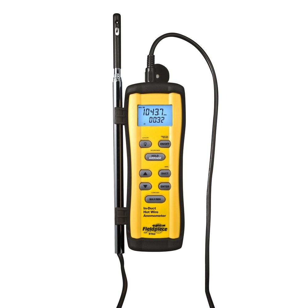
Fieldpiece STA2 In-Duct Hot Wire Anemometer
- Reads velocity inside the ventilation duct, where the rate has to be met
- Hot wire suits the low velocities a 50 to 120 cfm ventilation branch runs at
- Velocity times free area is the only way to confirm a required rate
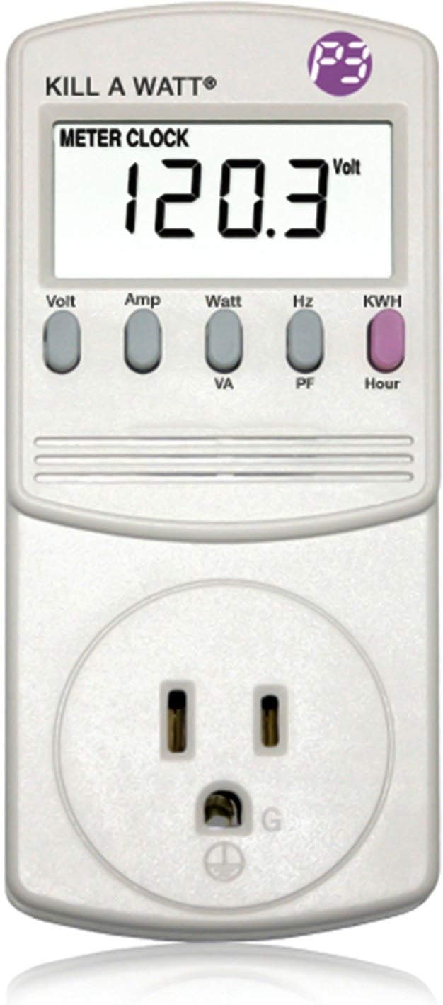
P3 P4400 Kill A Watt Electricity Usage Monitor
- Table N1103.6.1 is a cfm-per-watt test and watts is the half nobody measures
- A plug-in reading at the installed airflow is the field equivalent of HVI 916
- Turns a fan efficacy limit into a pass or a fail
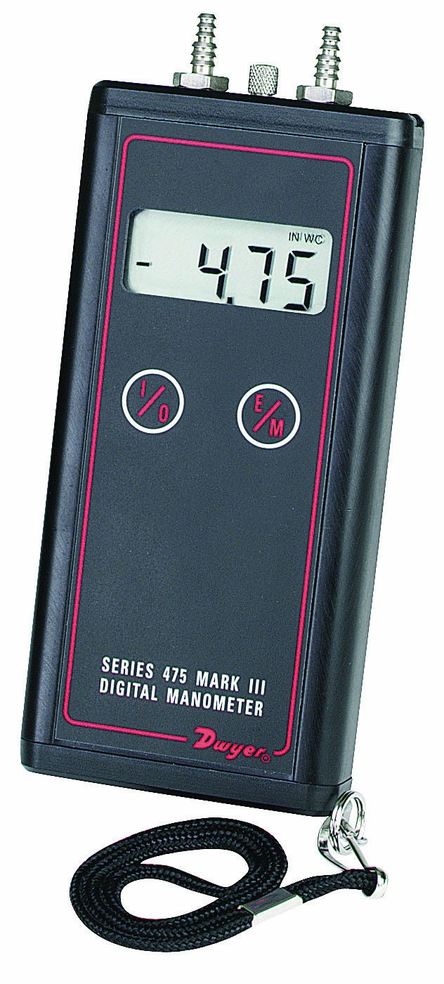
Dwyer Series 475 Mark III Digital Manometer
- Table M1505.4.4 footnote a requires the bathroom rate at not less than 0.25 in w.c.
- Free-air fan ratings say nothing about a real duct run and a roof cap
- Also the instrument for the external static pressure the system lives on
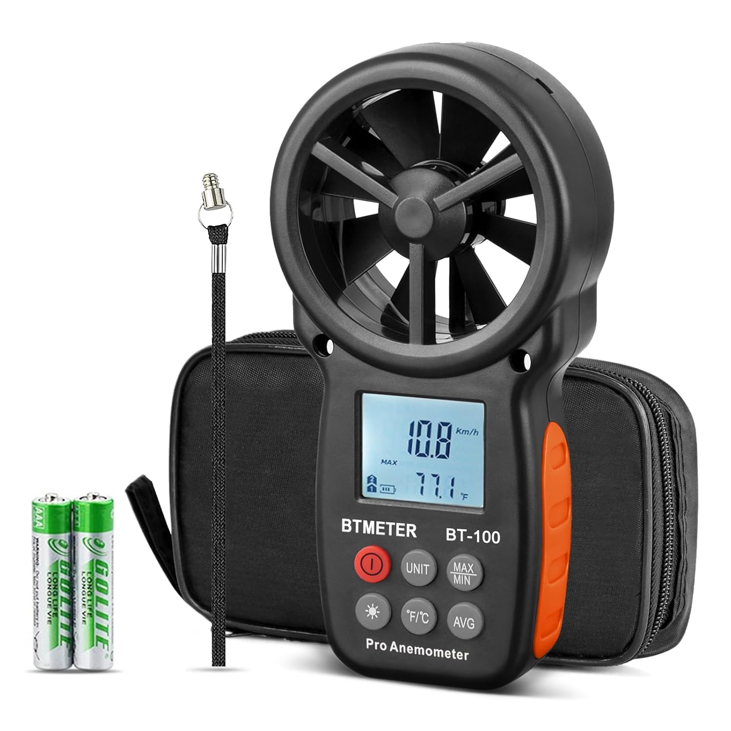
BTMETER BT-100 Handheld Anemometer
- Quick face-velocity traverse at a supply or exhaust grille
- Catches a ventilation fan delivering half its rating before you leave
- Cheap enough to live in the van next to the manometer
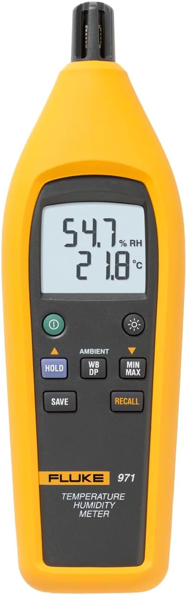
Fluke 971 Temperature Humidity Meter
- Indoor relative humidity is the outcome the ventilation rate is controlling
- Over-ventilating in a cold climate shows up as a dry house
- Under-ventilating shows as sustained high RH long before anybody complains
As an Amazon Associate, TestTalkHQ earns from qualifying purchases. Prices and availability can change.
Cause 5 — the controls, not the airflow
M1505.4.2 is one sentence and it fails jobs: “The whole-house mechanical ventilation system shall be provided with controls that enable manual override. Controls shall include text or a symbol indicating their function.”
An unlabelled toggle in a mechanical room fails it. A system hard-wired with no override fails it. A control buried inside a thermostat menu with no indication of what it does is an argument you may or may not win.
Fix: an engraved or printed label on the switch or the control, saying what it is. This is a five-minute item that regularly costs a re-inspection, and it has a real purpose beyond compliance — an unlabelled ventilation switch is a switch that gets turned off in February and never turned back on.
Cause 6 — fan efficacy, on the energy inspection
Airflow is a mechanical-code requirement. Watts per cfm is an energy-code requirement, and it is mandatory rather than a trade-off in a points table. Table N1103.6.1 / R403.6.1:
| Fan location | Airflow rate minimum (cfm) | Minimum efficacy (cfm/watt) | Airflow rate maximum (cfm) |
|---|---|---|---|
| HRV or ERV | Any | 1.2 | Any |
| Range hoods | Any | 2.8 | Any |
| In-line fan | Any | 2.8 | Any |
| Bathroom, utility room | 10 | 1.4 | < 90 |
| Bathroom, utility room | 90 | 2.8 | Any |
A 60 cfm bath fan is under 90, so the minimum is 1.4 cfm/W and the fan may draw no more than 42.9 W. Cheap fans miss this once they are working against real static, because the wattage climbs as the airflow falls — the same duct problem from Cause 1 shows up twice.
Cause 7 — local exhaust counted toward the whole-house rate
Table M1505.4.4 requires 100 cfm intermittent or 25 cfm continuous for a kitchen and 50 cfm intermittent or 20 cfm continuous for each bathroom. Those are separate requirements. They are neither added to the whole-house rate nor deducted from it, and a plan that shows “100 cfm range hood + 2 × 50 cfm bath fans = 200 cfm, whole-house requirement of 54 cfm satisfied” is wrong.
The confusion has a grain of truth in it, which is what makes it durable. M1505.4.1 does allow a local fan to serve as the whole-house system — but the fan then has to satisfy the larger of its two duties, and run on whatever schedule the whole-house requirement demands.
After it passes: the house tells you whether the rate was right
A system can be fully compliant and still be wrong for the building. Give it a few weeks and read the humidity:
| What you see | What it usually means | What to do |
|---|---|---|
| Winter indoor RH in the teens, static shocks, shrinking trim | Over-ventilating for a cold dry climate, often an oversized rate or a fan with no controls | Check which basis was used; consider intermittent operation with the correct factor; consider an ERV over an HRV |
| Sustained summer RH above about 60 percent, musty smell | Supply or exhaust ventilation dragging in humid outdoor air with no dehumidification | The rate is probably right; the latent load needs handling — see the sensible heat ratio calculator |
| Stale air, condensation on windows, odours lingering | Under-ventilating — usually the fan is not delivering its rating | Go back to Cause 1 and measure |
| Backdraft smell, soot marks, CO alarm on an atmospheric appliance | Exhaust-only system depressurising the house | Stop. Test worst-case depressurisation and check the appliance’s combustion air — see the combustion air opening calculator |