Whole-house ventilation is sized from two numbers every contractor already has: conditioned floor area and bedroom count. What makes it awkward is that there are two formulas in circulation, they look identical, and one asks for roughly twice as much air as the other. This walks the whole job: which rate governs, how to run each path, which credits are real and what they require, how to choose between an exhaust fan and an ERV, and how to commission the result so the house gets the air the paperwork promised.
First, which “ventilation” are we talking about?
The word does four unrelated jobs in a residential code book, and getting the wrong one is the fastest way to size the wrong thing:
| What people say | What it actually is | Where it lives |
|---|---|---|
| Whole-house ventilation | Continuous outdoor air for the occupants, sized from floor area and bedrooms | IRC M1505.4 / ASHRAE 62.2 — this article |
| Local exhaust | Kitchen and bathroom fans, sized per room | IRC Table M1505.4.4 |
| Combustion air | Free area of opening so a fuel-burning appliance can breathe | IFGC 304 / IRC G2407 — see the combustion air opening calculator |
| Attic ventilation | Net free vent area to keep a roof assembly dry | IRC R806 — see the attic ventilation calculator |
They are four different quantities in four different units, and satisfying one does nothing for the others. A house can have textbook attic venting, a correctly sized combustion air opening, a 100 cfm range hood, and still have no whole-house ventilation system at all.
The rate: two formulas that differ by one coefficient
Whole-house ventilation is sized from two numbers you already have — conditioned floor area and bedroom count. There are two formulas in circulation and they are not the same:
The bedroom term is identical — 7.5 cfm per bedroom plus one, which is the standard’s way of saying “two people in the first bedroom and one more per bedroom after that, at 7.5 cfm each.” The floor-area coefficient is three times larger in the standard, because ASHRAE tripled it in the 2013 edition of 62.2 and the IRC never followed.
62.2: 0.03 × 2,400 + 7.5 × 4 = 72 + 30 = 102 cfm
Same house, same inputs, 1.89 times the airflow. The gap widens with floor area, because that is the only term that differs — on a 4,800 sq ft five-bedroom it is 93 against 189 cfm.
Which one applies is a real decision with real consequences, and it is covered in its own article: IRC vs ASHRAE 62.2 ventilation rate. For the rest of this guide, assume you have settled it.
Running the IRC path
Section M1505.4.3 gives you two routes to the same requirement and lets you pick: the rate must be “not less than that determined in accordance with Table M1505.4.3(1) or not less than that determined by Equation 15-1.”
| Dwelling floor area (sq ft) | 0–1 bed | 2–3 bed | 4–5 bed | 6–7 bed | > 7 bed |
|---|---|---|---|---|---|
| < 1,500 | 30 | 45 | 60 | 75 | 90 |
| 1,501–3,000 | 45 | 60 | 75 | 90 | 105 |
| 3,001–4,500 | 60 | 75 | 90 | 105 | 120 |
| 4,501–6,000 | 75 | 90 | 105 | 120 | 135 |
| 6,001–7,500 | 90 | 105 | 120 | 135 | 150 |
| > 7,500 | 105 | 120 | 135 | 150 | 165 |
Table M1505.4.3(1), airflow in cfm. Every cell in it is Equation 15-1 evaluated at the top of its floor-area band and the top of its bedroom column. The 2,400 sq ft three-bedroom house is priced as though it were 3,000 sq ft with three bedrooms: 0.01 × 3,000 + 7.5 × 4 = 60 cfm, against 54 from the equation on the real house.
The 30 percent credit, and why most claims of it fail
Exception 1 to M1505.4.3 cuts the rate by 30 percent. It is the largest legitimate reduction on the IRC path, and it has two conditions joined by and:
| Condition | What it means on site | What fails it |
|---|---|---|
| A ducted system supplies ventilation air directly to each bedroom and to one or more of the living room, dining room or kitchen | Real duct to every sleeping room plus at least one main living space | A single central supply drop into the return plenum |
| The whole-house ventilation system is a balanced ventilation system | Roughly matched supply and exhaust — an HRV, an ERV, or a deliberately paired supply and exhaust fan | Exhaust-only. Supply-only. A bath fan running continuously. |
A beautifully ducted exhaust-only system does not qualify. A balanced ERV that dumps all its supply into one central point does not qualify. Both conditions, or no credit.
Equation path: 54 × 0.70 = 37.8 cfm. Table path: 60 × 0.70 = 42.0 cfm.
Leave the ERV supply as one central drop and it is 54 or 60 cfm — the credit is worth about 16 cfm of fan here, and the ducting that earns it is worth having anyway because it puts the outdoor air where people sleep.
Intermittent operation makes the fan bigger, not smaller
Exception 2 permits programmed intermittent operation. The instinct — run it half the time, buy half the fan — is exactly backwards. The rate is multiplied:
| Run-time in each 4-hour segment | 25% | 33% | 50% | 66% | 75% | 100% |
|---|---|---|---|---|---|---|
| Factor | 4 | 3 | 2 | 1.5 | 1.3 | 1.0 |
The same volume of outdoor air has to arrive in less running time, so the fan moves more air while it runs. Two constraints ride along: the controls must enable operation for not less than 25 percent of every 4-hour segment, and the table footnote permits interpolation between the listed run-times while expressly prohibiting extrapolation beyond them. There is no factor for 15 percent run time.
At 40 percent, interpolate between 33 percent (3) and 50 percent (2): 3 − (40−33)/(50−33) = 2.59, giving 139.8 cfm. Less run time, more fan, and a bigger duct to carry it.
In practice intermittent operation is worth it when the fan is an existing bath fan on a timer and continuous running would be noisy or would over-dry the house in winter. It is rarely worth it on a purpose-built HRV, which is quiet, efficient and designed to run.
Any trade

Contractor Job Estimator
Price remodels and GC work, then send a quote with no internal numbers.
Excel or Google Sheets. Best on a computer.
$29.00
BuyCheckout opens here — you stay on this page.
What you need on the van to prove any of this
Everything above is a requirement. None of it is a measurement, and the code is written about what the installed system does rather than what the carton claims. The gap between a fan rated 80 cfm and a fan moving 80 cfm through the duct somebody actually built is where whole-house ventilation quietly fails. Two of these measure air, one measures watts for the efficacy test, and one measures the static pressure the bathroom rate has to be met at.
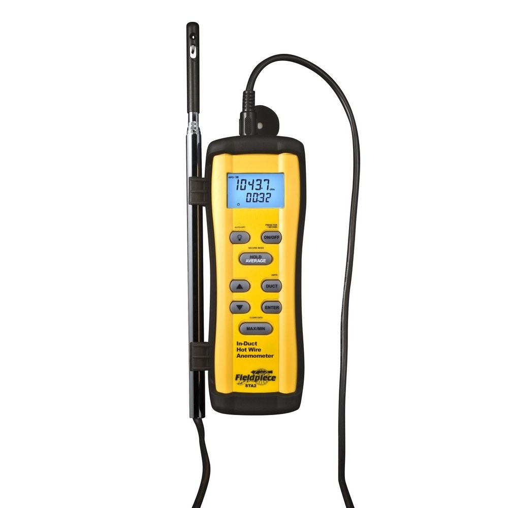
Fieldpiece STA2 In-Duct Hot Wire Anemometer
- Reads velocity inside the ventilation duct, where the rate has to be met
- Hot wire suits the low velocities a 50 to 120 cfm ventilation branch runs at
- Velocity times free area is the only way to confirm a required rate
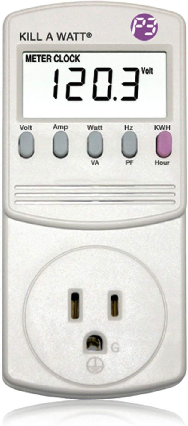
P3 P4400 Kill A Watt Electricity Usage Monitor
- Table N1103.6.1 is a cfm-per-watt test and watts is the half nobody measures
- A plug-in reading at the installed airflow is the field equivalent of HVI 916
- Turns a fan efficacy limit into a pass or a fail
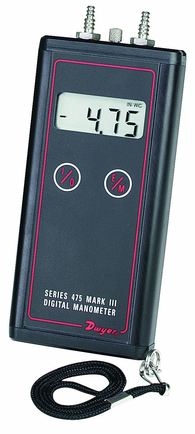
Dwyer Series 475 Mark III Digital Manometer
- Table M1505.4.4 footnote a requires the bathroom rate at not less than 0.25 in w.c.
- Free-air fan ratings say nothing about a real duct run and a roof cap
- Also the instrument for the external static pressure the system lives on
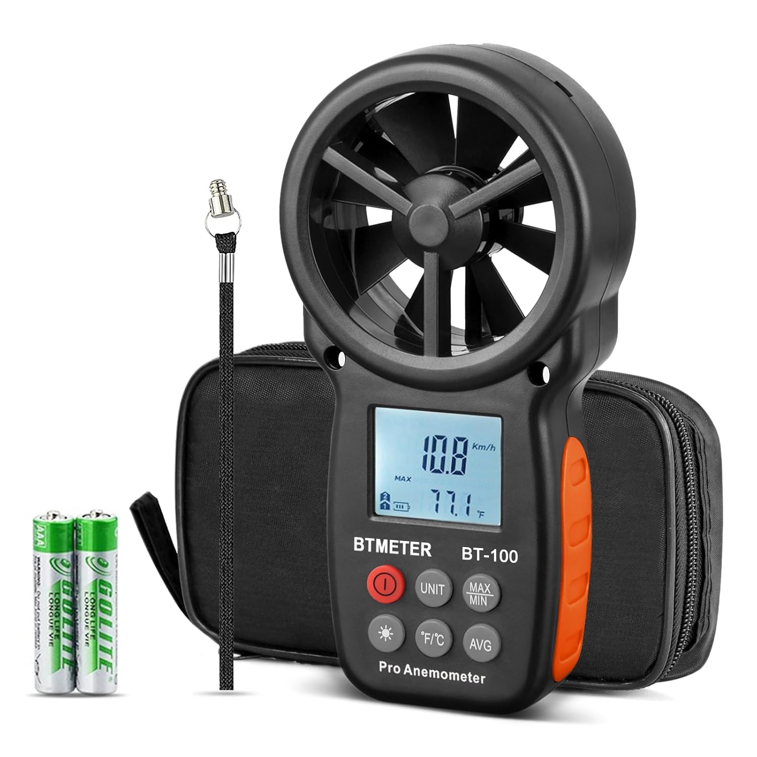
BTMETER BT-100 Handheld Anemometer
- Quick face-velocity traverse at a supply or exhaust grille
- Catches a ventilation fan delivering half its rating before you leave
- Cheap enough to live in the van next to the manometer
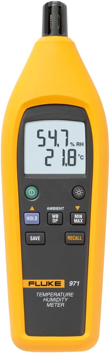
Fluke 971 Temperature Humidity Meter
- Indoor relative humidity is the outcome the ventilation rate is controlling
- Over-ventilating in a cold climate shows up as a dry house
- Under-ventilating shows as sustained high RH long before anybody complains
As an Amazon Associate, TestTalkHQ earns from qualifying purchases. Prices and availability can change.
Running the ASHRAE 62.2 path
62.2 starts from Qtot and then, optionally, credits some of the house’s natural infiltration against it:
Three things in there catch people out.
The bedroom floor. 62.2 says the bedroom count shall not be less than one, so a studio is treated as a one-bedroom. A 700 sq ft studio gets Qtot of 36 cfm. The IRC sets no such floor and its equation with zero bedrooms gives 14.5 cfm on the same unit, while its table gives 30. Three different answers for one studio, all correctly derived.
Occupant density. Section 4.1.3 assumes two people in a studio or one-bedroom and one more per additional bedroom. Where the actual occupancy is known to be higher, the rate goes up by 7.5 cfm per extra person. Six people in a three-bedroom is two above the assumed four, so Qtot goes from 102 to 117 cfm. A lower density may be used only where the authority having jurisdiction approves it, so this is not a reduction you take on your own initiative.
The two-thirds cap on the infiltration credit. No house, however leaky, can credit away more than two-thirds of its requirement. On the 2,400 sq ft three-bedroom, Qtot is 102 and the cap is 68 cfm; a normalized leakage of 0.35 produces an uncapped Qinf of 115 cfm, so the cap binds immediately and Qfan lands at 34 cfm rather than a negative number.
Choosing the system: exhaust, supply or balanced
The rate tells you how much air. It says almost nothing about how to move it. M1505.4.1 is deliberately permissive: “one or more supply or exhaust fans, or a combination of such,” and local fans are allowed to do the job, and an outdoor air duct tied into the return side of an air handler counts as supply ventilation.
| Type | What it does to the house | Best where | Watch for |
|---|---|---|---|
| Exhaust-only (continuous bath fan) |
Slight negative pressure; outdoor air enters through whatever leaks | Cold, dry climates; retrofits; tight budgets | Backdrafting atmospheric appliances; pulling air from a garage, crawlspace or attic; no 30% credit |
| Supply-only (outdoor air to the return) |
Slight positive pressure; you choose where air enters | Hot-humid climates, where you want to keep humid air out of the walls | Pushing indoor moisture into cold assemblies in winter; air handler runtime and PSC blower watts; no 30% credit |
| Balanced (HRV / ERV) |
Neutral pressure; filtered, tempered, ducted outdoor air | Anywhere the budget reaches, especially tight houses | Cost; commissioning; frost control in cold climates; needs full ducting to earn the 30% credit |
One more requirement that gets forgotten because it is not a number: M1505.4.2 says the whole-house system must have controls that enable manual override, and those controls must include text or a symbol indicating their function. An unlabelled switch in a mechanical room is a failed inspection, and it is also how systems get switched off and never switched back on.
Fan efficacy: the mandatory provision that catches cheap fans
Table N1103.6.1, published in the IECC as Table R403.6.1, sets a minimum airflow per watt. Read the columns carefully — the small numbers get misquoted as efficacies constantly:
| Fan location | Airflow rate minimum (cfm) | Minimum efficacy (cfm/watt) | Airflow rate maximum (cfm) |
|---|---|---|---|
| HRV or ERV | Any | 1.2 | Any |
| Range hoods | Any | 2.8 | Any |
| In-line fan | Any | 2.8 | Any |
| Bathroom, utility room | 10 | 1.4 | < 90 |
| Bathroom, utility room | 90 | 2.8 | Any |
The 10 and the 90 are minimum airflows, not efficacies. A small bath fan must manage 1.4 cfm/W; the same fan at 90 cfm or more must manage 2.8. A 60 cfm bath fan may therefore draw no more than 60 ÷ 1.4 = 42.9 W. Ratings are tested to HVI Standard 916, so compare against an HVI-certified listing and against the rating at 0.25 in w.c., not a free-air figure on the box.
Air handlers get an exception rather than a number: where an air handler integral to tested and listed HVAC equipment provides the whole-house ventilation, it must be powered by an electronically commutated motor. A PSC blower left running continuously for ventilation fails that, and costs a startling amount of electricity while it does.
Commission it, or you have designed a number rather than a system
Everything above produces a requirement. The code applies to the installed system, and the two are routinely different by a factor approaching two. A short commissioning sequence:
| Step | What to do | What good looks like |
|---|---|---|
| 1. Measure the flow | Velocity traverse in the ventilation duct, or a flow hood at the grille | Within about 10 percent of the required rate, and above it rather than below |
| 2. Measure the static | Manometer across the fan | At or below the pressure the fan was rated at — usually 0.25 in w.c. |
| 3. Measure the watts | Plug-in meter or clamp at the installed airflow | Flow ÷ watts at or above the Table N1103.6.1 minimum |
| 4. Check the controls | Manual override works; the control is labelled; any timer cannot be set below 25 percent | M1505.4.2 satisfied and the homeowner understands it |
| 5. Check the interactions | Worst-case depressurisation with atmospheric appliances; RH after a few weeks | No spillage; indoor RH in a sane band for the season |