
A flow coefficient is a measurement, not a dimension. Where the number comes from, why the gas equation needs psia and degrees Rankine, what happens at the sonic wall, and why n components in series each have to be the square root of n times larger.
What the number on the datasheet actually means
A flow coefficient is not a dimension you could measure with calipers. It is the result of a test. The manufacturer puts the component on a standard ISA rig, runs water through it, and records how many US gallons per minute pass while the pressure drop across it sits at exactly one psi. That figure is the Cv, and a component with a Cv of 2.0 passes twice the water of one with a Cv of 1.0 at the same drop.
The reason the trade needs such a thing is that a valve is not a hole. Air going through a quick coupler changes direction three or four times, squeezes past a ball detent, expands into a chamber and squeezes out again through a seat. No single bore measurement describes that path, and two couplers with identical 1/4 NPT threads can have internal flow paths that differ by a factor of three. The Cv collapses the whole geometry — the bore, the direction changes, the seat, the internal volume — into one number that can be compared across manufacturers and across body styles.
Why water, for an air fitting?
Because water is incompressible and therefore easy to test repeatably. The standard defines one test, run once, on a liquid, and the resulting coefficient is then used with a different equation when the medium is a gas. That is not a fudge. It is the same restriction either way; only the fluid behaviour changes, and the gas equation accounts for the change.
Why air needs absolute pressures
Water does not change density when you squeeze it. Air does. Push air through a restriction and it expands on the way out, so how much mass gets through depends on the absolute pressure on both sides, not merely on the difference between them.
That is the single most common mistake in hand calculations on air lines: working in psig. Every gas form of the flow coefficient equation wants psia — gauge pressure plus about 14.7 at sea level — and it wants absolute temperature as well, in degrees Rankine, which is Fahrenheit plus 460. The Swagelok valve sizing bulletin puts a one-line note right under its symbol list to that effect: p1 and p2 are absolute pressures for gas flow.
Q = 22.67 × Cv × √( Δp × p2 ÷ (Gg × T1) )
Once p2 ≤ ½ p1 (choked):
Q = 11.335 × Cv × p1 ÷ √( Gg × T1 )
Q in SCFM · p1, p2 in psia · Δp in psi
T1 = °F + 460 · Gg = 1.0 for air
The 22.67 is a published units constant, not a coefficient somebody tuned. It appears in the numerical constants table of the Swagelok MS‑06‑84 bulletin as the value of N2 for flow in std ft³/min, pressure in psia and temperature in degrees Rankine, alongside 6950 for standard litres per minute and bar. The Engineering ToolBox publishes the same gas equation in cubic feet per hour with a constant of 1360; divide by sixty and you get 22.67 again. Two independent publications, one number.
Temperature barely matters, and that is worth knowing
Absolute temperature enters under a square root, so it moves the answer very little. The bulletin states the range plainly: between −40 °F and +212 °F the whole correction factor is about +12% to −11%. Enter the real temperature for air coming straight off a compressor discharge with no aftercooler; for ordinary shop air at 70 to 100 °F, it is not where your error is coming from.
Any trade

Contractor Job Estimator
Price remodels and GC work, then send a quote with no internal numbers.
Excel or Google Sheets. Best on a computer.
$29.00
BuyCheckout opens in a new tab.
The hardware this argument is about
Every number on this page ends up as a decision about four cheap parts: the coupler, the plug that goes into it, the regulator and the filter. They are the restrictions, they are the things you can actually change, and they are almost always bought on thread size rather than on published flow. The hose behind them decides whether any of it survives.
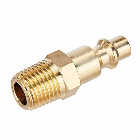
Amazon Basics Quick Connect Coupler & Plug Kit
- A coupler and its plug are two restrictions in series, not one
- Matched sets stop the mixed-profile fits that leak and strangle
- 14 pieces means the whole shop can run one consistent profile

LE LEMATEC Regulator & Flow Control Valve
- A gauge at the tool is how you catch a drop that only exists under flow
- 0–150 psi span covers ordinary shop supply pressures
- Set pressure at the tool, not at the tank, and the argument settles itself
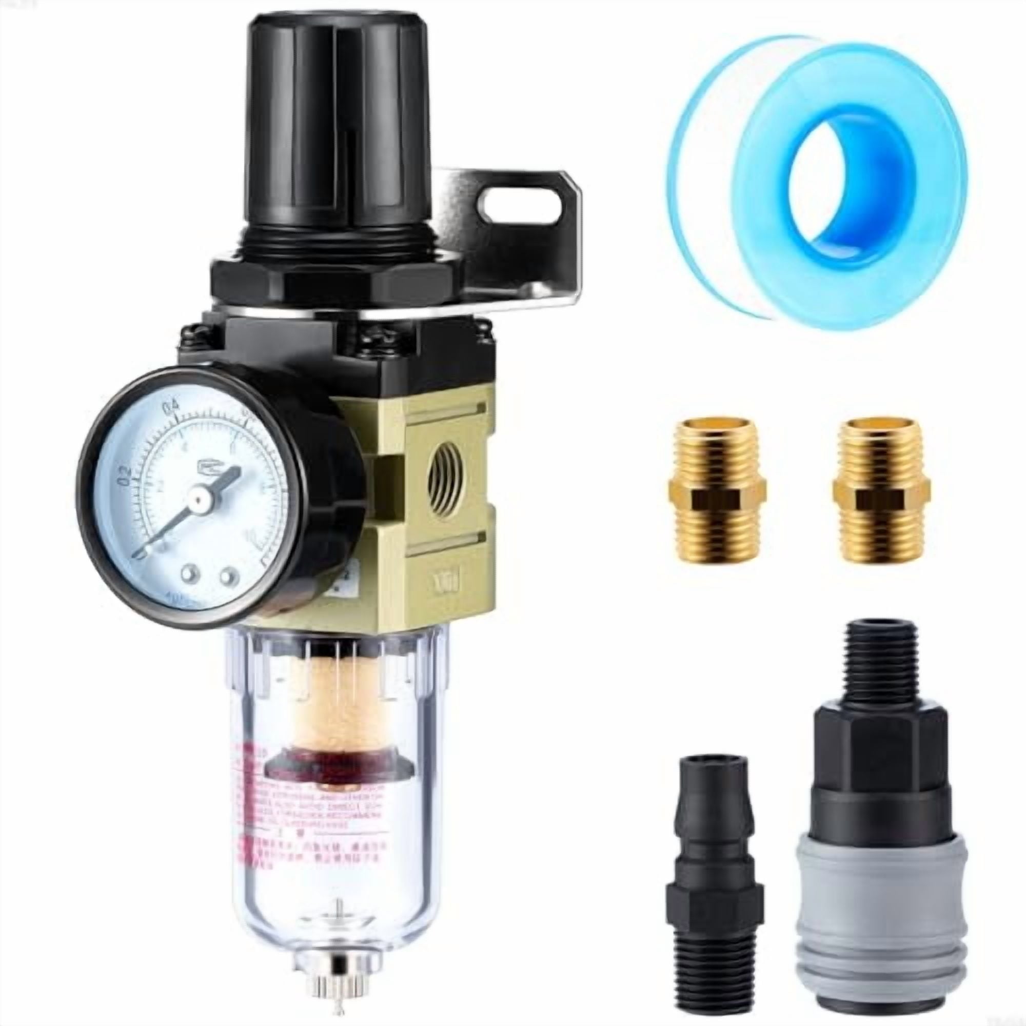
Hromee 1/4 in Filter Regulator AW2000-02
- Combines two of the series restrictions into one body
- A loading element raises the drop over time — the datasheet figure is the clean one
- Bowl drain keeps the element from becoming the restriction
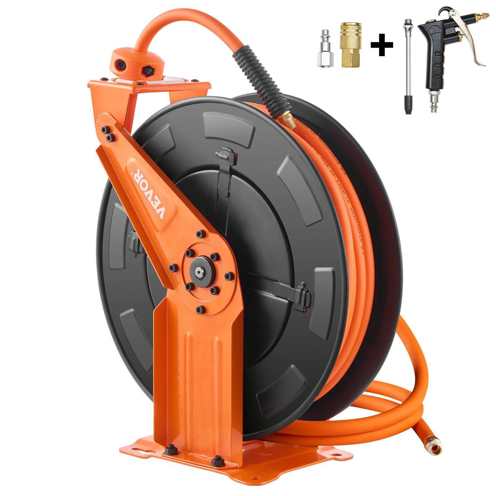
Relhost Retractable Air Hose Reel 3/8 in × 65 ft
- 3/8 in bore instead of 1/4 in is the cheapest flow upgrade on most lines
- Hose loss is friction over a length — a different calculation from Cv
- Right couplers behind an undersized hose just relocate the problem
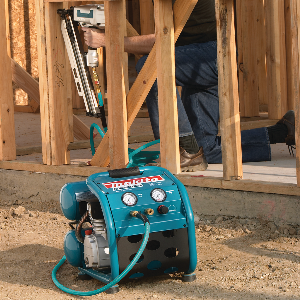
Makita MAC2400 Big Bore Air Compressor
- If supply pressure sags under load, no component choice fixes it
- Published delivered CFM at 90 psi is the comparable number, not horsepower
- Supply first, then components, then hose — in that order
As an Amazon Associate, TestTalkHQ earns from qualifying purchases. Prices and availability can change.
The sonic wall
Here is the behaviour that has no equivalent in water, and that catches people who reason about air by analogy with plumbing.
Open up the downstream side of a restriction and flow increases — up to a point. When the outlet pressure falls to half the absolute inlet pressure, the air leaves the orifice at the speed of sound. It cannot go faster. From that point on, reducing the downstream pressure further buys nothing whatsoever. You could connect the outlet to a vacuum pump and not get another cubic foot through.
The bulletin says it without hedging: “Any further decrease in outlet pressure does not increase flow, even if the outlet pressure is reduced to zero. Consequently, high pressure drop flow only depends on inlet pressure and not outlet pressure.”
On 90 psig shop air the threshold sits at an outlet of about 52 psia, which is roughly 38 psig, so a drop of about 52 psi. Tool feed legs never get near that; something has gone badly wrong before they do. Blow-off nozzles, cylinder exhaust ports, blowguns and anything venting to atmosphere are choked essentially all the time, which is exactly why an engineered blow-off nozzle and an open pipe stub of the same bore consume such different amounts of air.
Components in series, and the mistake everybody makes
Almost nobody has a single restriction between the header and the tool. The normal count is four: a filter, a regulator, a coupler and the plug that clips into it. Sometimes five, if there is a lubricator. The instinct is that four components sharing a 5 psi budget each get an easy job, about 1.25 psi apiece, so each can be smaller.
That is backwards. Pressure drop goes as the square of flow divided by Cv, so the coefficients combine as the sum of their reciprocal squares:
For n identical components: Cv,each = Cv,required × √n
Each of n equal components has to be √n times larger than a single component doing the whole job. Two components in series: 1.41× each. Three: 1.73× each. Four: 2.0× each. The assembly requirement does not get shared out; it gets harder for every part.
Absolute first: p1 = 90 + 14.696 = 104.696 psia; p2 = 99.696 psia. The sonic threshold is half of p1, 52.35 psia, and we are well above it — subcritical.
Cv = 25 × √530 ÷ (22.67 × √(5 × 99.696)) = 575.5 ÷ 506.1 = 1.137 for the whole assembly.
Its absolute choked ceiling is 58.6 SCFM, so there is real margin.
Now split it across a regulator, a coupler and a plug — three restrictions. Each one needs Cv 1.97, which is √3 × 1.137. Add a filter and make it four: Cv 2.27 each.
A Cv of 2.27 for a 1/4 in coupler is not something you will find in the bargain bin. That is the real lesson of the series rule: on a tight drop budget, ordinary fittings do not get you there, and the honest answers are a larger component size, fewer restrictions in the path, or a larger budget.
Where the Cv calculation stops
A flow coefficient describes a discrete component: a valve, a coupler, a plug, a regulator, a filter body, a fitting. It does not describe a length of pipe or hose. Loss along a run is friction over distance — a completely different equation with completely different inputs. Mixing the two is the most common way an air system goes wrong on paper. Size the distribution with the compressed air pipe size calculator and the pipe sizing guide, and the components with this one.
It also does not tell you how much air the job needs. That comes from the tool list and duty cycle — the per-tool CFM requirement calculator and chart are the right starting points — or from displacement if you are feeding actuators, which is what the cylinder air consumption calculator is for.
And it assumes the component is clean, correctly installed and flowing in its intended direction. Three qualifications that matter in the field:
- A loaded filter element is not its datasheet Cv. Elements gain pressure drop as they collect dirt and condensate. The differential indicator on a decent filter housing exists precisely to tell you how far from the clean figure you have drifted.
- Adaptors and reducers count. A 90° street elbow screwed straight into a coupler, or a reducing bushing to get from 3/8 to 1/4, is another restriction in series that the coupler’s own Cv does not include.
- Direction can matter. Some component geometries are not symmetric, and a datasheet may publish different figures for flow in each direction. Check before assuming.
Finally, a note on the arithmetic itself. The calculator prints a second opinion on every answer, computed from the bulletin’s own equations, which carry an expansion term instead of the outlet-pressure form. At a modest pressure drop the two agree within about 1%. Approaching the sonic point they diverge by around 6%. That spread is real and it is published, not an error — it is the honest width of an equation-based answer, and it is why final selection on a tight job belongs on the manufacturer’s own flow curve rather than on any formula.