Compressed Air Pipe Sizing & Layout Guide
Demand, drop budget, run length, and the layout details that decide the answer
Shop air is usually piped from whatever was on the shelf and then blamed on the compressor. This is the order the decisions actually go in, and the layout details that make a correctly calculated pipe size survive contact with a real shop.
The short version
Sizing shop air is four decisions in order: how much air you really draw at once, how much pressure you are willing to lose getting it there, how long the worst-case run actually is once fittings are counted, and only then what diameter satisfies both the drop budget and a sane velocity. Skip any of the first three and the fourth is a guess.
This guide covers the layout and the decisions. The arithmetic — Darcy-Weisbach at line density, Crane TP-410 fitting equivalents, velocity check across every common size — lives on the compressed air pipe size calculator.
Step 1 — find the demand that actually happens at once
The number that sizes pipe is simultaneous demand, not the sum of every tool you own and not the compressor nameplate. A one-person shop almost never runs two air tools at the same time, so the sizing flow is the largest single tool plus a realistic allowance for blowguns and leaks. A two-bay shop with a helper is a genuinely different number.
Two habits produce wrong answers here. The first is adding up every tool on the wall, which produces a main sized for a shop that does not exist. The second is using the compressor's rated SCFM, which describes what the supply can make, not what the distribution has to carry — those are only the same number if the compressor is running flat out continuously.
- Intermittent tools — impact wrenches, ratchets, nailers — are duty-cycle loads. Their catalogue SCFM is the figure while the trigger is down.
- Continuous tools — sanders, grinders, blast cabinets, paint guns — draw their rated flow for as long as they run, and these are what set pipe size in most shops.
- Leaks are a real, permanent load. An older shop carrying 10 to 20 percent of capacity in leakage is unremarkable.
Work the simultaneous figure out properly with the per-tool CFM requirement calculator, then bring that number here.
Step 2 — set a pressure drop budget and split it
A pressure drop target is not a single number applied to the pipe. It is a budget spread across the whole path from receiver to tool, and the hard-piped main is usually the smallest share of it. The benchmark used by the Compressed Air Challenge and the US Department of Energy's compressed air sourcebook is to keep total distribution loss low — commonly stated as no more than about ten percent of discharge pressure, with a design target of roughly two to three psi from receiver to point of use.
| Segment | Typical budget | Notes |
|---|---|---|
| Header / main run | 1 - 2 psi | The part this calculator sizes |
| Drop leg and take-off | 0.3 - 0.5 psi | Usually small if the drop is not undersized |
| Filter / regulator / lubricator | 1 - 3 psi | Rises sharply as the filter element loads |
| Hose and quick-couplers | 2 - 10 psi | Frequently the single largest loss in the system |
Read that table twice. A 50 ft length of 1/4 inch hose with a cheap coupler can lose more pressure than every foot of hard pipe in the building. Sizing the main to a fraction of a psi while feeding tools through a garden-hose-sized whip is a very common and very expensive way to be precise about the wrong thing.
Every 2 psi of extra discharge pressure costs roughly 1 percent more compressor power, permanently. A sloppy 10 psi distribution loss is about 5 percent on the electric bill for the life of the system — which is exactly why the budget exists.
Step 3 — measure the run you actually have
Pipe sizing uses the longest path from the receiver to the furthest point of use, not an average and not a straight-line distance across the floor. Follow the pipe: up the wall, along the joists, around the obstruction, back down to the far bench.
Then count fittings, because an elbow is not free. Crane Technical Paper No. 410 expresses each fitting's resistance as a length-to-diameter ratio, which converts to feet of equivalent pipe once the diameter is known. On 1 inch pipe a standard 90 degree elbow is worth about 2.6 ft of straight run, and a tee taken through the branch is worth about 5.2 ft.
The practical lesson is that long sweeping bends and fewer branch tees buy real pressure back, and that a tangled short run can be worse than a clean long one.
Gear that decides whether your pipe size survives contact with the shop
The main is only one link. These are the parts that most often become the new restriction once the pipe itself is right.
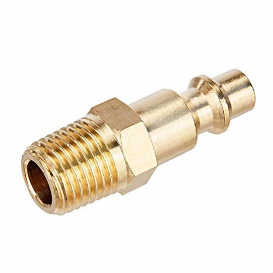
Quick Connect Brass Coupler Kit
Industrial-interchange couplers with a decent bore, so the last two inches of the system are not the biggest restriction in it.
View on Amazon
Regulator & Flow Control 0-150 PSI
Lets you set pressure at the point of use instead of raising header pressure to paper over distribution losses.
View on Amazon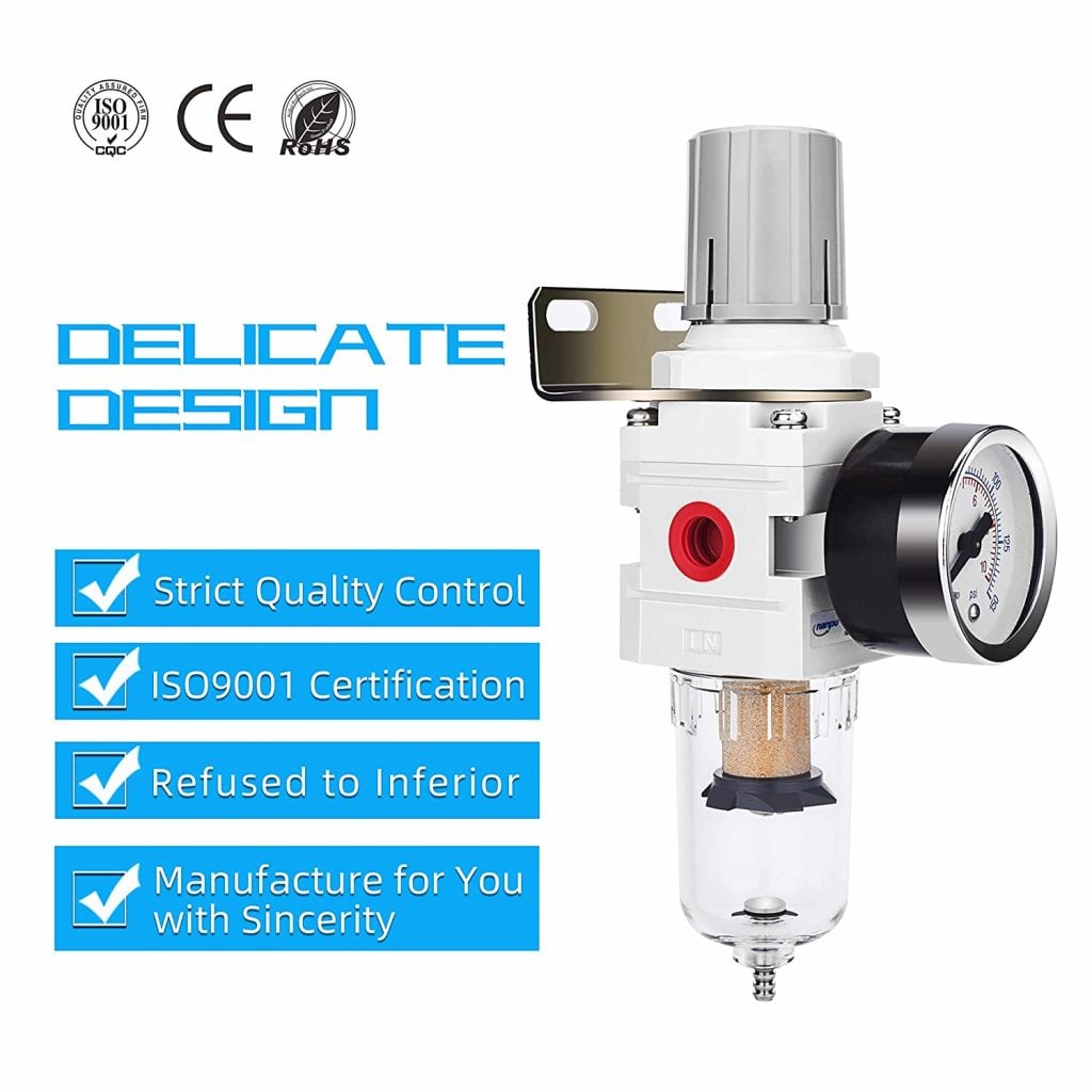
Filter / Regulator Combo
Water and scale in the bore raise real pressure drop over time. A filter at each drop keeps the pipe you sized behaving like the pipe you sized.
View on Amazon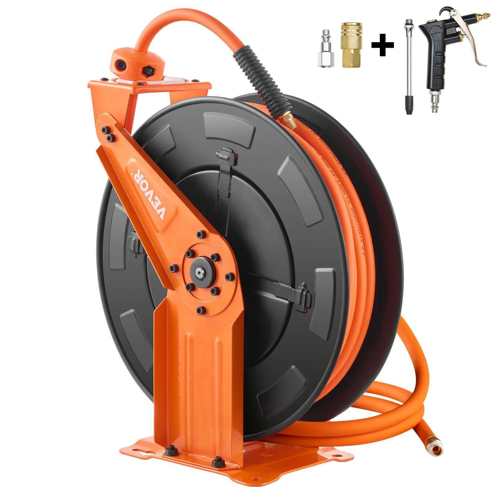
Relhost 65ft Retractable Reel
A 3/8 in bore instead of 1/4 in is frequently worth more real psi at the tool than one step up in hard pipe.
View on Amazon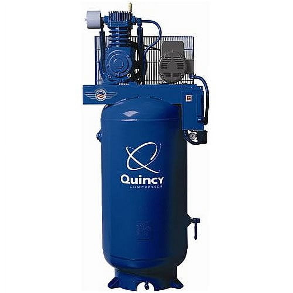
Quincy QT-7.5 80-Gallon
Receiver volume smooths the peak draws that a steady-flow pipe calculation assumes away.
View on AmazonAs an Amazon Associate, TestTalkHQ earns from qualifying purchases. Prices and availability can change.
Step 4 — loop the main if the shape of the shop allows it
A dead-end main feeds the furthest drop from one direction, so the full run length applies. A closed loop feeds it from two directions, so the flow splits and the effective length to the worst-case point is roughly half the loop. That is a meaningful win for very little extra pipe: on the same diameter, halving effective length roughly halves the pressure drop.
A loop also evens out the pressure across the shop, so the bench at the far corner behaves like the one next to the receiver, and it makes adding a drop later a local job rather than a reason to re-size everything downstream.
- To size a loop, enter half the total loop length as the run length in the calculator.
- Valve the loop so a section can be isolated for repair without shutting the whole shop down.
- A loop is not a fix for an undersized main — it buys roughly one step of effective length, not one step of diameter.
Step 5 — take off from the top, drop down, and leave a drip leg
Compressed air leaving a compressor is saturated, and it condenses as it cools in the pipe. Water collects on the bottom of the main. Every take-off detail that follows exists for that one reason.
- Take off from the top of the main, with a gooseneck over the top before dropping down. Liquid water sits on the bottom of the pipe, so a bottom take-off feeds it straight to the tool.
- Run the drop past the take-off and terminate it in a short capped drip leg with a drain. That is where condensate lands instead of in the regulator.
- Slope the main slightly — on the order of an inch per twenty feet — toward a drip leg or drain at the low end, so the pipe empties itself rather than storing water.
- Put the filter and regulator at the drop, after the drip leg, so they handle vapour rather than slugs of liquid.
Water in the bore is not just a finish problem. It corrodes black iron from the inside, and the scale that results roughens and narrows the pipe, which raises real pressure drop over the years relative to the number you calculated on day one.
Step 6 — size it, then sanity-check velocity
With demand, budget, length and fitting count in hand the diameter falls out of the pressure drop equation. The calculator runs it for every common size so you can see where the cliff is — and in a typical shop the cliff is sharp, because drop scales with roughly the fifth power of diameter. One step up in pipe often cuts pressure drop by three quarters.
Pressure drop is not the only check. Velocity matters because fast-moving air strips liquid water and scale off the pipe wall and carries it to the tools, and it makes drop legs far less effective at separating condensate. Common design practice keeps mains at or below about 20 ft/s and branches below about 30 ft/s, so the calculator's recommendation has to satisfy both the drop target and the velocity ceiling.
Run your own numbersThe pipe size calculator gives pressure drop and velocity for every common size at your flow, pressure, run length and fitting count.
Open the calculatorWhen the calculated answer sits right on a size boundary, go up. Oversized air pipe costs material once and costs nothing in energy afterwards, and the extra volume behaves as useful storage. Undersized pipe is a permanent tax you pay in compressor power and in tools that never quite perform.
Layout mistakes that undo a correct calculation
- Using PVC or CPVC. Both become brittle with age and oil exposure and can shatter into fragments under stored pressure. Manufacturers exclude compressed air service. Use steel, copper, stainless, or an aluminium or composite system listed for compressed air.
- Feeding the shop off the compressor's discharge rather than the receiver. The receiver is what absorbs pulsation and peak draw.
- Undersized drops off a correctly sized main. A 1/2 inch drop on a 1-1/4 inch main throws away what the main saved.
- Bottom take-offs. The cheapest possible way to send water to the tool.
- Long 1/4 inch whips and low-flow couplers. The most common real bottleneck in a shop that has otherwise been piped correctly.
- Raising header pressure to compensate. It works, and it costs about 1 percent more power for every 2 psi, forever.
Frequently asked questions
What size compressed air pipe do I need for a typical home shop?
Size by flow and distance rather than by shop size. A single-user shop drawing 15 to 20 SCFM over a 100 ft run at 100 psig is normally comfortable in 3/4 inch Schedule 40, while a continuous sander or blast cabinet at 40 to 60 SCFM over the same distance typically needs 1 inch or 1-1/4 inch. Run the actual numbers rather than relying on shop square footage.
Should I run a loop or a straight main?
Loop it if the shape of the building allows. A closed loop feeds the far drop from two directions, so the effective run length is roughly half the loop, which roughly halves the pressure drop for very little extra pipe. It also evens out pressure across the shop and makes adding drops later a local job.
Why take air off the top of the pipe?
Liquid condensate collects on the bottom of a compressed air main. A take-off from the bottom feeds that water directly to the tool. A gooseneck over the top of the pipe, with the drop continuing past the take-off into a capped drip leg, sends water to the drain instead.
How much pressure drop is acceptable in shop air piping?
A common design target is two to three psi from receiver to point of use, with total distribution loss held under about ten percent of discharge pressure. The important part is budgeting across the whole path, since hose and quick-couplers usually lose more than the hard-piped main.
Is it worth oversizing compressed air pipe?
Usually yes. Larger pipe costs material once and costs nothing in energy afterwards, the extra internal volume acts as useful storage, and it leaves room for the shop to grow. The practical rule is never to go below the calculated size and to step up when the answer lands near a boundary.
Related calculators & guides
Shop air is usually piped from whatever was on the shelf and then blamed on the compressor. This is the order the decisions actually go in, and the layout details that make a correctly calculated pipe size survive contact with a real shop.
The short version
Sizing shop air is four decisions in order: how much air you really draw at once, how much pressure you are willing to lose getting it there, how long the worst-case run actually is once fittings are counted, and only then what diameter satisfies both the drop budget and a sane velocity. Skip any of the first three and the fourth is a guess.
This guide covers the layout and the decisions. The arithmetic — Darcy-Weisbach at line density, Crane TP-410 fitting equivalents, velocity check across every common size — lives on the compressed air pipe size calculator.
Step 1 — find the demand that actually happens at once
The number that sizes pipe is simultaneous demand, not the sum of every tool you own and not the compressor nameplate. A one-person shop almost never runs two air tools at the same time, so the sizing flow is the largest single tool plus a realistic allowance for blowguns and leaks. A two-bay shop with a helper is a genuinely different number.
Two habits produce wrong answers here. The first is adding up every tool on the wall, which produces a main sized for a shop that does not exist. The second is using the compressor's rated SCFM, which describes what the supply can make, not what the distribution has to carry — those are only the same number if the compressor is running flat out continuously.
- Intermittent tools — impact wrenches, ratchets, nailers — are duty-cycle loads. Their catalogue SCFM is the figure while the trigger is down.
- Continuous tools — sanders, grinders, blast cabinets, paint guns — draw their rated flow for as long as they run, and these are what set pipe size in most shops.
- Leaks are a real, permanent load. An older shop carrying 10 to 20 percent of capacity in leakage is unremarkable.
Work the simultaneous figure out properly with the per-tool CFM requirement calculator, then bring that number here.
Step 2 — set a pressure drop budget and split it
A pressure drop target is not a single number applied to the pipe. It is a budget spread across the whole path from receiver to tool, and the hard-piped main is usually the smallest share of it. The benchmark used by the Compressed Air Challenge and the US Department of Energy's compressed air sourcebook is to keep total distribution loss low — commonly stated as no more than about ten percent of discharge pressure, with a design target of roughly two to three psi from receiver to point of use.
| Segment | Typical budget | Notes |
|---|---|---|
| Header / main run | 1 - 2 psi | The part this calculator sizes |
| Drop leg and take-off | 0.3 - 0.5 psi | Usually small if the drop is not undersized |
| Filter / regulator / lubricator | 1 - 3 psi | Rises sharply as the filter element loads |
| Hose and quick-couplers | 2 - 10 psi | Frequently the single largest loss in the system |
Read that table twice. A 50 ft length of 1/4 inch hose with a cheap coupler can lose more pressure than every foot of hard pipe in the building. Sizing the main to a fraction of a psi while feeding tools through a garden-hose-sized whip is a very common and very expensive way to be precise about the wrong thing.
Every 2 psi of extra discharge pressure costs roughly 1 percent more compressor power, permanently. A sloppy 10 psi distribution loss is about 5 percent on the electric bill for the life of the system — which is exactly why the budget exists.
Step 3 — measure the run you actually have
Pipe sizing uses the longest path from the receiver to the furthest point of use, not an average and not a straight-line distance across the floor. Follow the pipe: up the wall, along the joists, around the obstruction, back down to the far bench.
Then count fittings, because an elbow is not free. Crane Technical Paper No. 410 expresses each fitting's resistance as a length-to-diameter ratio, which converts to feet of equivalent pipe once the diameter is known. On 1 inch pipe a standard 90 degree elbow is worth about 2.6 ft of straight run, and a tee taken through the branch is worth about 5.2 ft.
The practical lesson is that long sweeping bends and fewer branch tees buy real pressure back, and that a tangled short run can be worse than a clean long one.
Gear that decides whether your pipe size survives contact with the shop
The main is only one link. These are the parts that most often become the new restriction once the pipe itself is right.
Quick Connect Brass Coupler Kit
Industrial-interchange couplers with a decent bore, so the last two inches of the system are not the biggest restriction in it.
Regulator & Flow Control 0-150 PSI
Lets you set pressure at the point of use instead of raising header pressure to paper over distribution losses.
Filter / Regulator Combo
Water and scale in the bore raise real pressure drop over time. A filter at each drop keeps the pipe you sized behaving like the pipe you sized.
Relhost 65ft Retractable Reel
A 3/8 in bore instead of 1/4 in is frequently worth more real psi at the tool than one step up in hard pipe.
Quincy QT-7.5 80-Gallon
Receiver volume smooths the peak draws that a steady-flow pipe calculation assumes away.
As an Amazon Associate, TestTalkHQ earns from qualifying purchases. Prices and availability can change.
Step 4 — loop the main if the shape of the shop allows it
A dead-end main feeds the furthest drop from one direction, so the full run length applies. A closed loop feeds it from two directions, so the flow splits and the effective length to the worst-case point is roughly half the loop. That is a meaningful win for very little extra pipe: on the same diameter, halving effective length roughly halves the pressure drop.
A loop also evens out the pressure across the shop, so the bench at the far corner behaves like the one next to the receiver, and it makes adding a drop later a local job rather than a reason to re-size everything downstream.
- To size a loop, enter half the total loop length as the run length in the calculator.
- Valve the loop so a section can be isolated for repair without shutting the whole shop down.
- A loop is not a fix for an undersized main — it buys roughly one step of effective length, not one step of diameter.
Step 5 — take off from the top, drop down, and leave a drip leg
Compressed air leaving a compressor is saturated, and it condenses as it cools in the pipe. Water collects on the bottom of the main. Every take-off detail that follows exists for that one reason.
- Take off from the top of the main, with a gooseneck over the top before dropping down. Liquid water sits on the bottom of the pipe, so a bottom take-off feeds it straight to the tool.
- Run the drop past the take-off and terminate it in a short capped drip leg with a drain. That is where condensate lands instead of in the regulator.
- Slope the main slightly — on the order of an inch per twenty feet — toward a drip leg or drain at the low end, so the pipe empties itself rather than storing water.
- Put the filter and regulator at the drop, after the drip leg, so they handle vapour rather than slugs of liquid.
Water in the bore is not just a finish problem. It corrodes black iron from the inside, and the scale that results roughens and narrows the pipe, which raises real pressure drop over the years relative to the number you calculated on day one.
Step 6 — size it, then sanity-check velocity
With demand, budget, length and fitting count in hand the diameter falls out of the pressure drop equation. The calculator runs it for every common size so you can see where the cliff is — and in a typical shop the cliff is sharp, because drop scales with roughly the fifth power of diameter. One step up in pipe often cuts pressure drop by three quarters.
Pressure drop is not the only check. Velocity matters because fast-moving air strips liquid water and scale off the pipe wall and carries it to the tools, and it makes drop legs far less effective at separating condensate. Common design practice keeps mains at or below about 20 ft/s and branches below about 30 ft/s, so the calculator's recommendation has to satisfy both the drop target and the velocity ceiling.
Run your own numbersThe pipe size calculator gives pressure drop and velocity for every common size at your flow, pressure, run length and fitting count.
When the calculated answer sits right on a size boundary, go up. Oversized air pipe costs material once and costs nothing in energy afterwards, and the extra volume behaves as useful storage. Undersized pipe is a permanent tax you pay in compressor power and in tools that never quite perform.
Layout mistakes that undo a correct calculation
- Using PVC or CPVC. Both become brittle with age and oil exposure and can shatter into fragments under stored pressure. Manufacturers exclude compressed air service. Use steel, copper, stainless, or an aluminium or composite system listed for compressed air.
- Feeding the shop off the compressor's discharge rather than the receiver. The receiver is what absorbs pulsation and peak draw.
- Undersized drops off a correctly sized main. A 1/2 inch drop on a 1-1/4 inch main throws away what the main saved.
- Bottom take-offs. The cheapest possible way to send water to the tool.
- Long 1/4 inch whips and low-flow couplers. The most common real bottleneck in a shop that has otherwise been piped correctly.
- Raising header pressure to compensate. It works, and it costs about 1 percent more power for every 2 psi, forever.
Frequently asked questions
What size compressed air pipe do I need for a typical home shop?
Size by flow and distance rather than by shop size. A single-user shop drawing 15 to 20 SCFM over a 100 ft run at 100 psig is normally comfortable in 3/4 inch Schedule 40, while a continuous sander or blast cabinet at 40 to 60 SCFM over the same distance typically needs 1 inch or 1-1/4 inch. Run the actual numbers rather than relying on shop square footage.
Should I run a loop or a straight main?
Loop it if the shape of the building allows. A closed loop feeds the far drop from two directions, so the effective run length is roughly half the loop, which roughly halves the pressure drop for very little extra pipe. It also evens out pressure across the shop and makes adding drops later a local job.
Why take air off the top of the pipe?
Liquid condensate collects on the bottom of a compressed air main. A take-off from the bottom feeds that water directly to the tool. A gooseneck over the top of the pipe, with the drop continuing past the take-off into a capped drip leg, sends water to the drain instead.
How much pressure drop is acceptable in shop air piping?
A common design target is two to three psi from receiver to point of use, with total distribution loss held under about ten percent of discharge pressure. The important part is budgeting across the whole path, since hose and quick-couplers usually lose more than the hard-piped main.
Is it worth oversizing compressed air pipe?
Usually yes. Larger pipe costs material once and costs nothing in energy afterwards, the extra internal volume acts as useful storage, and it leaves room for the shop to grow. The practical rule is never to go below the calculated size and to step up when the answer lands near a boundary.