
Most combustion air work goes wrong in one of three places, and none of them is the arithmetic. It goes wrong when somebody totals the wrong appliances, when somebody cuts the hole to the net free area and then screws a louver over it, or when somebody runs the duct sideways because that was the easy route and never notices the code just doubled the opening. The ratios themselves are the simplest part of the job. This is the order to do the whole thing in, and the parts a calculator cannot do for you.

Step 1 — total the input rating, not the appliance you came for
Every ratio in Section 304 is applied to the total input rating of all appliances in the space. Not the one you are replacing. Not the biggest one. All of them, added together, in Btu per hour, from the data plates rather than from memory.
This is the single most common way a correctly calculated installation ends up undersized, and it happens because the job is framed as a furnace change-out. The furnace is 100,000 Btu/h, the opening gets sized for 100,000 Btu/h, and the 40,000 Btu/h water heater that has been in the same closet for fifteen years is never counted. The real requirement was 140,000 Btu/h — forty percent more opening than was installed.
Get the input rating from the plate. If you are still specifying the appliance, the furnace sizing calculator is the right place to settle the heating input first, because it is that number — not the output, not the tonnage — that everything here is driven by. The same total is also what sizes the gas piping, which is worth doing in the same sitting: see gas pipe sizing.
Input rating is not output, and not the old plate
Two traps. The first is reading the output (Btu/h out) instead of the input (Btu/h in) on a modern condensing plate — the input is the number the code means, and it is the larger of the two. The second is an appliance that has been derated or had an orifice change and still wears the factory plate. Where there is any doubt, clock the meter.
Step 2 — choose which of the five methods you are using
These are alternatives, not a checklist. You satisfy one.
| Method | Code | What it asks for | Realistic when |
|---|---|---|---|
| All outdoor air, two openings, direct or vertical duct | 304.6.1 | 1 in² free area per 4,000 Btu/h, each opening | The default. Cheapest hole per Btu of any outdoor method. |
| All outdoor air, two openings, horizontal ducts | 304.6.1 | 1 in² per 2,000 Btu/h, each opening | Only when you genuinely cannot go vertical. Doubles the opening. |
| All outdoor air, one opening | 304.6.2 | 1 in² per 3,000 Btu/h, and ≥ the vent connector total | Smallest total free area, but adds clearance requirements. |
| All indoor air | 304.5 | 50 ft³ per 1,000 Btu/h, or the infiltration formula | Open older basements. Hopeless in a closet. |
| Mechanical supply | 304.9 | 0.35 cfm per 1,000 Btu/h from outdoors | Commercial and engineered work. Requires burner interlock. |
For a 140,000 Btu/h pair of appliances those come out as 35 in² per opening, 70 in² per opening, one 46.7 in² opening, 7,000 ft³ of room, and 49 cfm respectively. The choice between the first two is usually made by whoever is holding the tin snips, which is exactly the problem — it is a factor-of-two decision and it should be made deliberately.
Why horizontal costs double
Buoyancy. Air arriving through a vertical duct from a ventilated crawl space falls into the room; air leaving through a vertical duct to a ventilated attic rises out of it. A horizontal duct through a rim joist gets no help at all, so the code doubles the area to compensate. It also closes the obvious dodge: 304.11 states that a horizontal upper combustion air duct “shall not slope downward toward the source of combustion air”.
HVAC
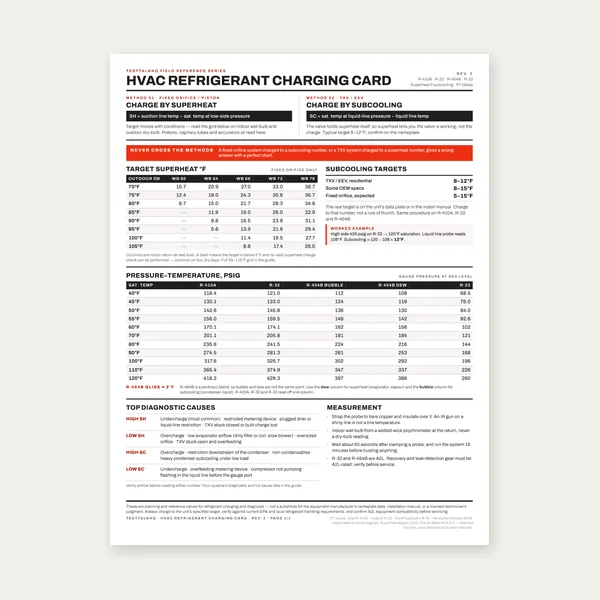
HVAC Refrigerant Charging Card
$3.99
Buy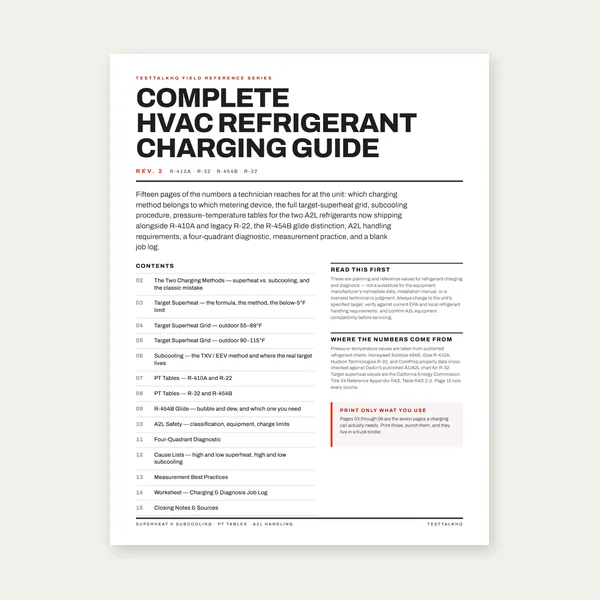
Complete HVAC Charging Guide
$12.99
Buy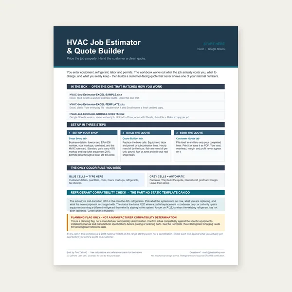
HVAC Job Estimator
$29.00
Buy
HVAC Complete Bundle
$39.00
BuyCheckout opens here — you stay on this page.
The instruments this job actually needs
Combustion air is one of the few areas where the paperwork and the reality come apart completely. An installation can satisfy every ratio in Section 304 and still spill, and the only way to know which you have is to measure. Three readings settle almost every case: the pressure in the appliance space under worst-case conditions, whether air is genuinely moving through the lower opening, and whether the vent connector ever gets hot. Louvers, grilles and combustion air ducts are sheet-metal goods bought locally, so TestTalkHQ does not link them.
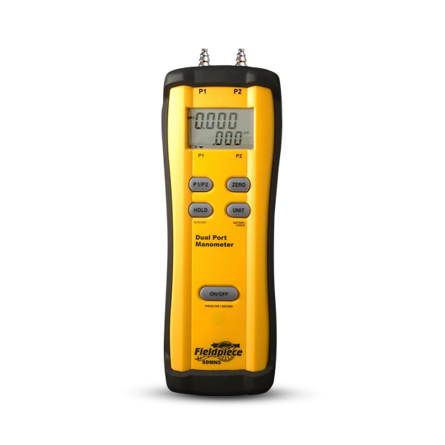
Fieldpiece SDMN5 Dual-Port Manometer
- Reads the depressurization the appliance space is actually under
- Dual port references the room against outdoors in one reading
- Turns a calculated opening into a tested one
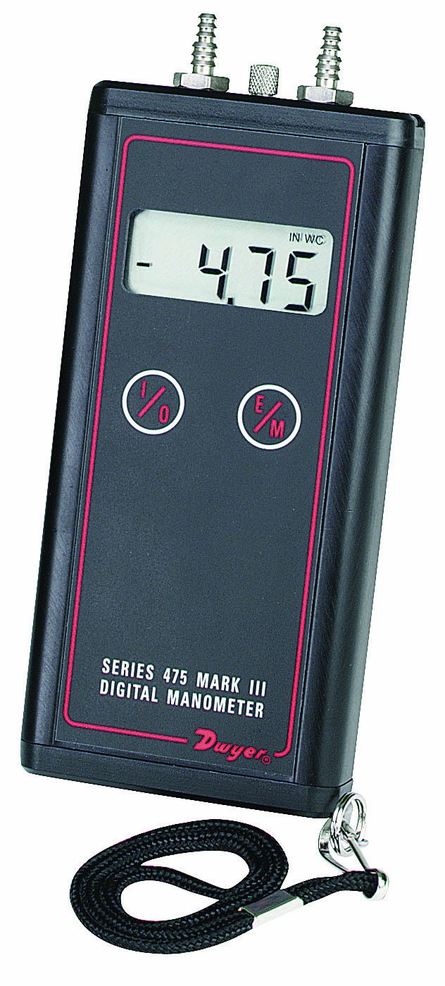
Dwyer Series 475 Mark III Manometer
- Resolution down where room depressurization lives
- Also reads draft at the diverter and static in the duct
- A long-standing reference instrument for this work
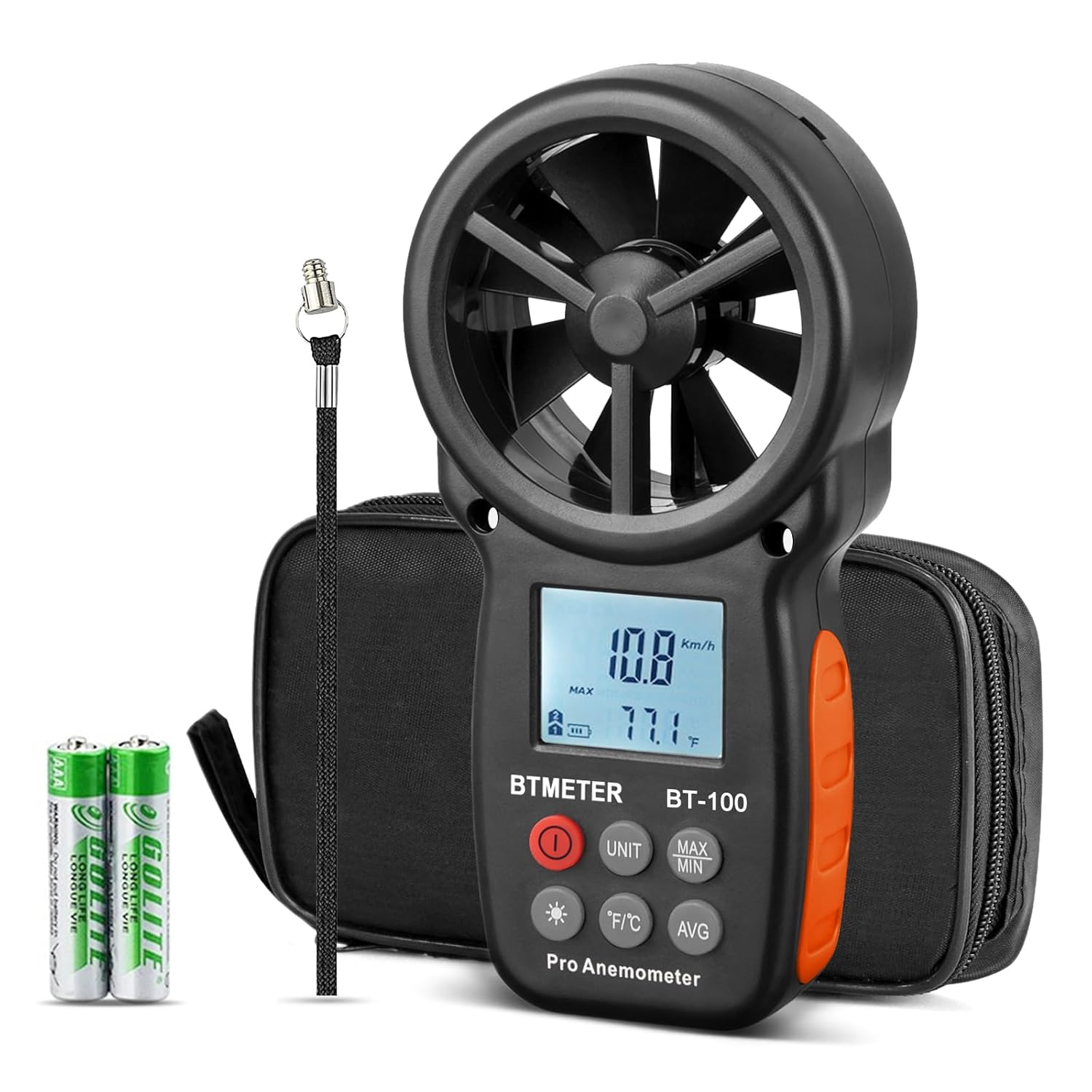
BTMETER BT-100 Handheld Anemometer
- Confirms the lower opening is feeding rather than exhausting
- Catches a louver blanked off behind insulation or paint
- Velocity × free area is the air the room really gets
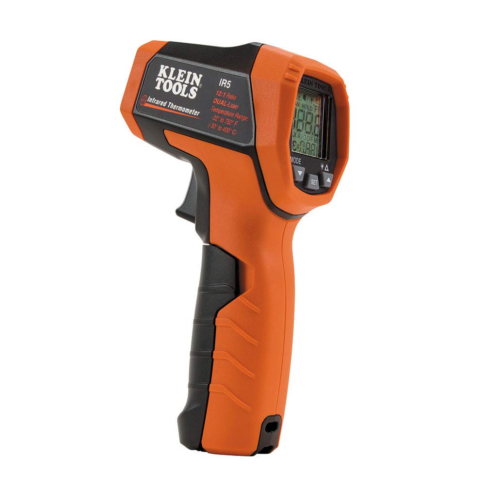
Klein Tools IR5 Infrared Thermometer
- Reads the draft hood and vent connector without contact
- A connector that never warms up is one that never drew
- Dual laser keeps the spot where you aimed it
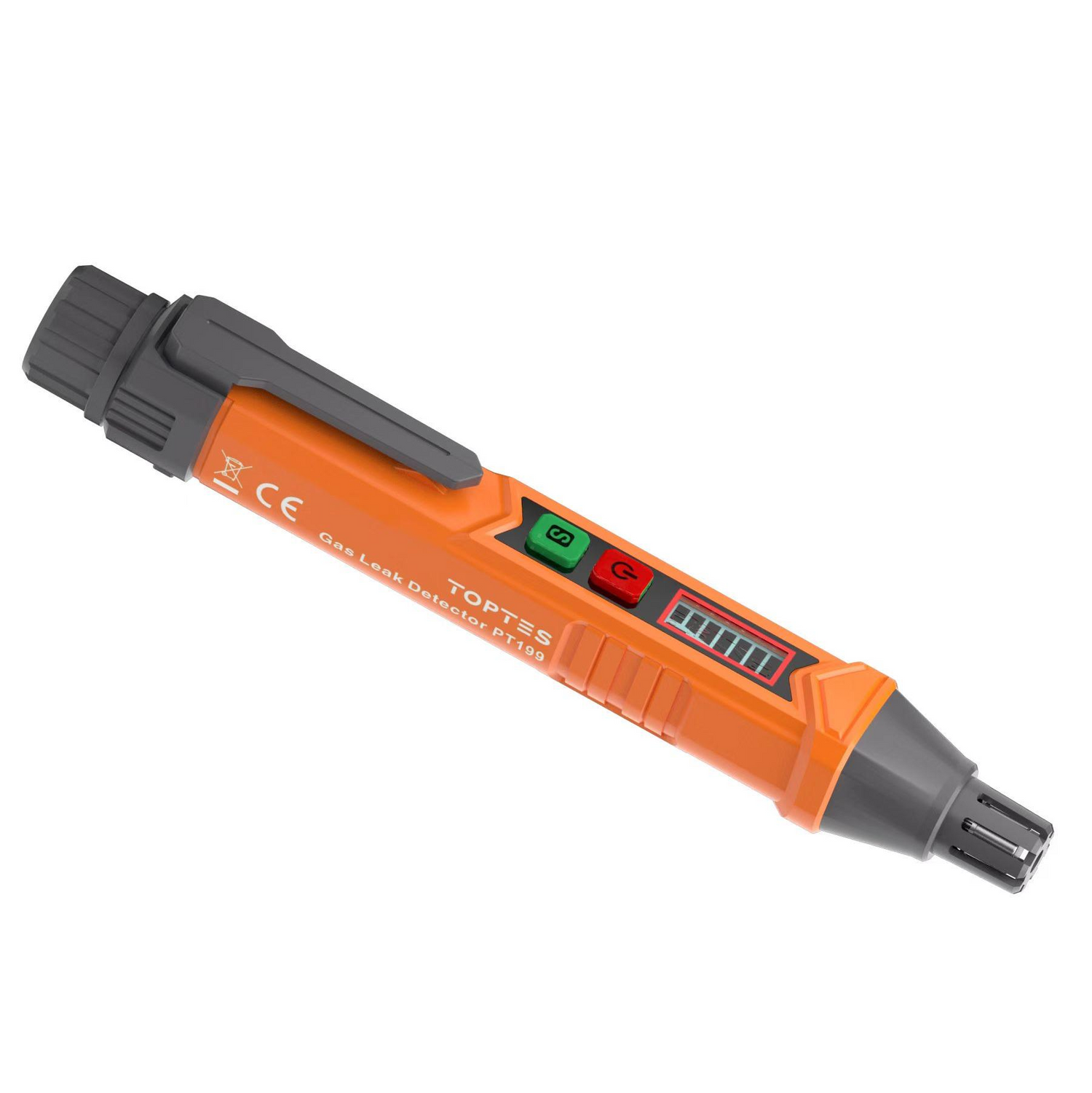
PT199 Natural Gas Leak Detector
- Rides in the bag alongside the manometer on any gas call
- Audible and visual alarm for combustible gas
- Does not replace a CO monitor — carry both
As an Amazon Associate, TestTalkHQ earns from qualifying purchases. Prices and availability can change.
Step 3 — size the free area, then size the hole
These are two different numbers and conflating them is the error that survives every other check, because the arithmetic was right.
Gross opening (in²) = net free area ÷ (louver net free area % ÷ 100)
Section 304.10 says the required size of openings “shall be based on the net free area of each opening”, and that where the free area of a louver is known from the manufacturer, that figure is used. Only where it is genuinely unknown do the deemed percentages apply — and there are two competing sets of them:
| Covering | Fuel gas code (IFGC 304.10 / IRC G2407.10) | Mechanical code (IMC 709.1) | Gross opening for 35 in² free |
|---|---|---|---|
| Metal louver or grille | 75% | — | 46.7 in² |
| Metal louver or grille | — | 60% | 58.3 in² |
| Wood louver | 25% | — | 140 in² |
| Wood louver | — | 10% | 350 in² |
| Plain opening, nothing over it | 100% | 35 in² | |
Those are not a transcription error. The two codes genuinely deem different free areas for the same unknown louver, and which one applies depends on what your jurisdiction has adopted for the appliance in question. The practical answer is to stop assuming: get the manufacturer’s published net free area for the louver you are actually buying, because it is printed per size and it is usually worse on small louvers than on large ones.
The 3 inch minimum, and why slots fail
Section 304.6 requires that “the minimum dimension of air openings shall be not less than 3 inches”, and the same 3 in floor appears again at 304.5.3.1 for openings combining indoor spaces. It exists because a long thin slot of the same area does not flow like a compact opening — the boundary layer takes a disproportionate share of it. Any time the area you need is being squeezed into a fixed joist or stud bay, check the other dimension before you cut.
Step 4 — the parts no calculator can do for you
Area is where most people stop. The inspection is where the rest of it shows up.
Where the openings go
- Two-opening method: one opening commencing within 12 inches of the top of the enclosure and one within 12 inches of the bottom. Not roughly. Not both low because the joists were in the way.
- One-opening method: the single opening commences within 12 inches of the top, and the appliance must have clearances of not less than 1 inch from the sides and back and 6 inches from the front. A water heater shoved against a stud wall disqualifies the method however good the opening is.
- Exterior intakes: 304.11 requires the lowest side of a combustion air intake opening on the exterior of a building to be not less than 12 inches above the adjoining finished ground level. In snow country that clearance is the difference between an opening and a drift.
Duct rules that catch people out
Section 304.11 is short and every clause in it has teeth:
- Ducts of galvanized steel per Chapter 16, or equivalent corrosion resistance, strength and rigidity. Inside dwelling units, unobstructed stud and joist spaces may convey combustion air provided not more than one required fireblock is removed.
- Ducts terminate in an unobstructed space allowing free movement of air to the appliances — not behind the furnace cabinet, not into a corner stacked with paint tins.
- A duct serves a single enclosure, and one duct shall not serve both upper and lower openings. The separation between upper and lower ducts must be maintained all the way back to the source. Teeing one duct into two openings defeats the whole point of having a high one and a low one.
- Ducts terminating in an attic space shall not be screened.
- Horizontal upper ducts shall not slope downward toward the source of combustion air.
- The space around a liner, gas vent or plastic piping inside a chimney shall not be used to supply combustion air.
Screens, louvers, dampers and the sign
Screens must be no finer than ¼ inch mesh, and whatever they block comes off your free area. Non-motorized louvers and grilles must be fixed in the open position — a louver somebody can close in winter is not a compliant louver. Motorized louvers must be interlocked with the appliance so they are proven full open before main burner ignition and throughout operation, with means to prevent ignition if they fail to open and to shut the burner down if they close while running. Manually operated dampers are not permitted in combustion air openings at all. The mechanical code adds a requirement worth honouring everywhere: a permanent sign in clear view adjacent to the openings, letters at least 1 inch high, reading “Louvers, dampers and/or ventilation openings must not be blocked or disabled.”