What the snowbank actually pulls on each attachment, where the published method comes from, why the vendor spacing table answers a different question, and six real roofs worked from the drawing to the device count
Two questions, and only one of them is on the chart
Snow retention arguments nearly always collapse once you separate two questions that get asked as one:
- How much force is the snowbank applying? That depends on the design snow load, the pitch, and how far it is from the eave to the ridge. It does not depend at all on what product you have chosen.
- What does it take to hold that force? That depends entirely on the tested capacity of one attachment and the factor of safety you apply to it. It does not depend on the roof except through the answer to question one.
A vendor spacing chart keyed on roof pitch answers neither. It answers a third question — where do the devices go — which is genuinely useful and genuinely not the same thing. The force method has been published for years in the trade engineering literature, it is three multiplications long, and the reason to learn it is that it catches the one failure mode a chart cannot: a heavily loaded roof getting the same layout as a lightly loaded one.
IIBEC — the International Institute of Building Enclosure Consultants — publishes it as a sentence rather than an equation, and the sentence is worth reading closely because every clause is load-bearing: “Vector force is found by reducing the vertical load (lb/ft² or kPa) by the sine of the roof angle. The product is then multiplied by the tributary area (ft² or m²) to the snow guard system. The loads for the entire length from eave to ridge are tributary to the snow guard system restraining it. For standing-seam metal roof (SSMR) profiles, tributary force is distributed to each point of system attachment—the standing seams.”
The Construction Specifier publishes the same method in almost the same words, and so does Rocky Mountain Snow Guards. Three independent sources, one method. That is about as settled as trade engineering gets.
Stage one: the sine of the roof angle is doing all the work
Snow sits on a roof and pulls straight down. On a slope, that pull splits into a part pressing into the deck and a part trying to slide down the surface. The sliding part is the sine of the roof angle times the total, and that is the entire slope term in the calculation.
The angle itself comes from the pitch: θ = arctan(rise ÷ 12). No lookup table needed, and the numbers are worth having in your head because they move faster than people expect:
| Pitch | Angle | sin θ | Share of the weight trying to slide |
|---|---|---|---|
| 2:12 | 9.5° | 0.1644 | 16% |
| 3:12 | 14.0° | 0.2425 | 24% |
| 4:12 | 18.4° | 0.3162 | 32% |
| 5:12 | 22.6° | 0.3846 | 38% |
| 6:12 | 26.6° | 0.4472 | 45% |
| 8:12 | 33.7° | 0.5547 | 55% |
| 10:12 | 39.8° | 0.6402 | 64% |
| 12:12 | 45.0° | 0.7071 | 71% |
Going from 4:12 to 6:12 is 41 per cent more sliding force on an otherwise identical roof. That is why measuring the built pitch rather than reading the drawn one is not fussiness — a 41 per cent error in a term is enough to move a row count.
Why the snow load has to come from somewhere else
The first number in the chain is the design roof snow load in pounds per square foot, and this guide is not going to derive it for you, because it is a substantial calculation in its own right with exposure, thermal, slope and importance factors, and because getting it wrong at that stage poisons everything downstream. Three ways to get it honestly: the structural drawings, the local code amendment, or an ASCE 7 Chapter 7 calculation. If you need to do that calculation, we have it covered separately — the roof snow load calculator and the roof snow load guide walk the whole path, and ground snow load vs roof snow load exists because confusing the two is the single most common way this goes wrong.
The short version of that confusion: ground snow load is the big number on the map, roof snow load is what reaches the roof after the reductions, and feeding the ground number into a retention calculation will have you buying hardware for a roof you do not have.
Stage two: the tributary area, and the two ways people halve it
Vector force is in pounds per square foot. To get pounds on a device you multiply by the area of roof that device is responsible for — and that area is where the mistakes live.
The up-slope dimension is the whole rafter, eave to ridge. Not half of it, not the horizontal span, not the building width. IIBEC says it flatly: “the loads for the entire length from eave to ridge are tributary to the snow guard system restraining it.” The snow halfway up the slope is not holding itself up; on a slippery roof the whole blanket is leaning on whatever is at the bottom. On a gable roof each slope is a separate problem with its own rafter length.
The across-slope dimension is the attachment spacing. On a standing seam roof that is the panel cover width, because clamps go on the seams and that is where the load lands. Cover width, not sheet width — a 16 inch panel is typically sold off a wider coil. This is the input that quietly breaks a repeat job: a 24 inch panel hands every clamp 33 per cent more force than an 18 inch panel on a roof that is otherwise identical. Same snow, same pitch, same rafter, same product, and a system that worked last year fails this year.
The published worked example, which is the one to check any calculator against. From IIBEC:
Design roof snow 35 lb/ft²; slope 6:12 (sin 26.565° = 0.447); eave to ridge 40 ft; panel width 18 in.
35 × 0.447 × 40 × 1.5 = 938.7 lb per panel seam.
At full precision (sin θ = 0.4472) it is 939.1 lb. The 0.4 lb gap is the published text rounding the sine to three places.
Nine hundred and thirty-nine pounds, per seam, on a completely unremarkable roof. Strip the panel width out and you get the figure to compare against a continuous rail quoted per foot: 626 lb for every lineal foot of eave. A thirty-foot eave is 9.4 tons of snow trying to leave the building in one piece.
Any trade

Contractor Job Estimator
Price remodels and GC work, then send a quote with no internal numbers.
Excel or Google Sheets. Best on a computer.
$29.00
BuyCheckout opens in a new tab.
The one input that is actually on the roof
Two of the three terms that set the demand come off paper. The pitch comes off the roof, and it is the term that moves fastest: a roof drawn 4:12 and built 6:12 is 41 per cent more sliding force, which can be the difference between two rows and three. Measure it. The rest of the list is layout and staying attached to the building while you work above the eave.
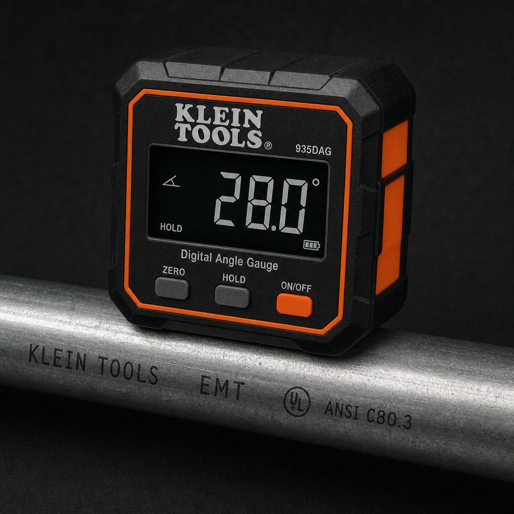
Klein Tools 935DGGP Digital Angle Gauge
- Reads the actual roof angle in degrees, which is what sin θ needs
- Magnetic base sits on a panel rib instead of fighting a shingle course
- Settles a drawn pitch against a built pitch in about ten seconds

TAJIMA Chalk‑Rite CR301JF Jam‑Free Chalk Line
- Straight rows up the slope, which is the whole point of a staggered pattern
- Jam-free crank for the repeated pulls a multi-row layout takes
- Fine line, so a clamp lands on the mark and not a half inch off it
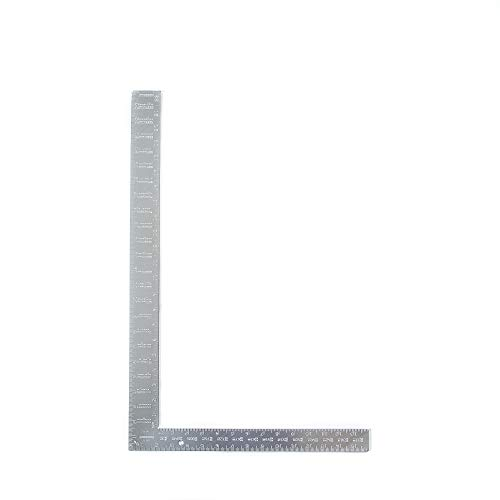
Swanson TA122 Aluminum Rafter Square 16×24
- Reads pitch directly from a rafter or a panel, no batteries involved
- Doubles as the layout square for the first row off the eave
- The cross-check when a digital gauge gives you a number you doubt
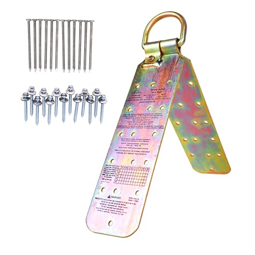
Guardian 00455 Temper Reusable Roof Anchor
- A mid-slope row means time spent above the eave on a slippery panel
- Reusable anchor rather than a nail-through plate left behind
- The honest cost line on a multi-row layout nobody quotes for

Garelick 89421 21‑Foot Aluminum Snow Roof Rake
- Retention means the snow stays on the roof, which is a load you now own
- Reach for the eave zone where the bank densifies deepest
- Aluminium sections, for the retrofit where the structure is the weak link
As an Amazon Associate, TestTalkHQ earns from qualifying purchases. Prices and availability can change.
Run your own roof. The snow guard spacing calculator takes the design snow load, the pitch, the eave-to-ridge rafter length, the seam spacing and the device capacity, and returns the vector force, the tributary force on every attachment, the allowable capacity after your factor of safety, the rows required and the minimum tested ultimate strength to shop for.
Stage three: ultimate, allowable, and the mistake that gets printed on datasheets
Now the product side. One number matters and it is not a catalogue headline: the tested ultimate holding capacity of one attachment, on the actual panel profile you are installing, from a test report.
That is not a stylistic preference, it is what the building code requires. Section 1608.9 of the IBC-family text on snow guards says the effectiveness of proprietary snow guard systems “shall be demonstrated by tests.” Sheffield Metals describes what that looks like in practice for S-5!: “each clamp is tested on actual roof panels until failure… At least three samples are tested per configuration.” A capacity measured on somebody else’s seam is not a capacity for yours.
Then divide. The Metal Construction Association calls for a minimum factor of safety of 2.0 on the tested failure load, as IIBEC records, and S-5! recommends the same. Construction Canada spells out why in the bluntest terms available:
So a 1,000 lb device is a 500 lb device. The practical trap when using any calculator: if the number you have is already an allowable or working load, set the factor of safety to 1.0, or you de-rate it twice and buy hardware you did not need. If the number is an ultimate, leave the factor at 2.0. Getting those two backwards in the dangerous direction is exactly the failure Construction Canada is describing.
From allowable capacity to a row count
Divide the demand by the allowable and round up. With the published example: 939 ÷ 500 = 1.88, so two rows, each attachment then carrying 470 lb — 94 per cent of allowable, which is tight but inside. To do it in a single row you would need a tested ultimate of 939 × 2 = 1,878 lb, and that reversed figure is the genuinely useful one when you are shopping rather than sizing.
Sharing the load across rows rests on an assumption worth stating: the snowbank bridges. IIBEC puts it as “the snowbank creates a bridge between rows to distribute vector loads,” and the reason it works is compressive strength in the pack — “because the compressive strength is so great at the snow-roof interface, snow guard devices only a few inches in height have demonstrated success even when snowbanks are quite deep.” Bridging is a property of the snow and the device geometry, not something arithmetic can confirm.
Where the rows go, which is a different kind of knowledge
The force calculation tells you how many. It is close to silent on where, and IIBEC is refreshingly honest about that: “Further and exact placement details are more related to art and aesthetics than science.” What it does offer is one firm principle and one firm practice.
The principle is that the snowbank is strongest at the bottom. “Gravitational forces compress the snowbank the most at its interface with the roof surface, especially toward its lower (eave) end, so that is where compressive strength is greatest.” The practice follows from it: “Even when the calculation of vector force indicates that multiple rows are required, the common global practice is to locate the snow-retention devices within the downslope half of the roof surface.”
For the detail below that, the prescriptive vendor guidelines earn their keep. snowguards.com publishes a spacing guide whose practical content is real:
- Start the first row 24 to 36 inches up from the eave. Their reason: it “allows the first 2 – 3 feet of snow to shed off roof, preventing snow accumulation at the eaves.” It also keeps the first row out of the ice-and-water zone and away from the gutter.
- Stagger rows course to course rather than stacking devices in columns up the slope.
- Horizontal spacing by panel width: panels under 12 inches get “one snow guard in the center of every other panel”; panels over 12 inches get one per panel, alternating one-third and two-thirds in from the seam row to row. Flat seam, rubber, TPO, PVC and glass get 24 inches apart.
- Vertical row spacing by slope, from 34 inches at 1:12 and 2:12 down to 24 inches at 6:12, 18 inches at 8:12 and 9:12, and 14 inches at 12:12.
- Above 12:12, a caveat in their own words: “do not expect 100% result. Guards may only act to break up snow on very steep slopes.”
So why not just use the table?
Because it is keyed on slope alone, and slope is one of three terms. Run the same 6:12 roof — 40 ft rafter, 18 inch panels, a 500 lb allowable device — across a realistic range of snow loads and the engineered answer moves while the chart does not:
| Design snow load | Vector force | Force per 18 in seam | Rows at 500 lb allowable | Chart row spacing |
|---|---|---|---|---|
| 20 psf | 8.94 psf | 537 lb | 2 | 24 in |
| 30 psf | 13.42 psf | 805 lb | 2 | 24 in |
| 35 psf | 15.65 psf | 939 lb | 2 | 24 in |
| 50 psf | 22.36 psf | 1,342 lb | 3 | 24 in |
| 70 psf | 31.30 psf | 1,878 lb | 4 | 24 in |
| 90 psf | 40.25 psf | 2,415 lb | 5 | 24 in |
Two rows or five, same chart row. That gap is the whole argument.
There is a more subtle version worth understanding, though, because it stops you dismissing the chart as simply wrong. Run the vendor’s own printed calculation method on the default roof — rafter in inches, subtract 36 at the eave, divide by the 24 inch row height — and it asks for 18 rows against the force method’s two. Share 939 lb of demand across 18 rows and each device carries about 52 lb. That is exactly the capacity class of a small adhesive or screw-down pad guard. The prescriptive table is calibrated for the discontinuous, many-small-units style of system; a 1,000 lb seam clamp is a different animal. Both layouts resist the same force. They are just answering for different hardware, which is the subject of the pads, rails or fence comparison.
One honest wrinkle: slope length or horizontal projection?
This does not appear in any of the published write-ups, and an engineer checking your numbers will find it, so it is better to know about it.
ASCE 7’s sloped-roof snow load acts on the horizontal projection of the roof. The vector force method multiplies by the rafter length measured along the slope. Those describe different areas: a 40 foot rafter at 6:12 covers only 35.8 feet of horizontal run.
Work the published example rigorously on a horizontal-projection basis and you get 840 lb per seam instead of 939. The industry convention is larger by exactly 1/cos θ — 11.8 per cent at 6:12, 41 per cent at 12:12. So the published method is conservative, and conservative is the right direction for a device whose failure sends a slab of snow onto whatever is below. Size to the published convention; just know which number you are holding if you ever have to reconcile two calculations that disagree by about the cosine of the roof angle.
Six roofs, drawing to device count
Every figure below is the same four multiplications and one division. The point of running six is to show how little it takes to move the answer.
| Roof | Load / pitch / rafter / panel | Vector force | Per attachment | Device (ult / FOS) | Rows | Then carries |
|---|---|---|---|---|---|---|
| Mountain cabin | 70 psf, 10:12, 22 ft, 16 in | 44.81 psf | 1,315 lb | 1,200 / 2.0 = 600 lb | 3 | 438 lb (73%) |
| Suburban garage, pad guards | 25 psf, 4:12, 18 ft, 16 in | 7.91 psf | 190 lb | 150 / 2.0 = 75 lb | 3 | 63 lb (84%) |
| Commercial entrance canopy | 40 psf, 3:12, 60 ft, 24 in | 9.70 psf | 1,164 lb | 1,500 / 2.0 = 750 lb | 2 | 582 lb (78%) |
| Church nave | 45 psf, 12:12, 35 ft, 12 in | 31.82 psf | 1,114 lb | 1,000 / 2.0 = 500 lb | 3 | 371 lb (74%) |
| Long barn slope | 50 psf, 6:12, 80 ft, 24 in | 22.36 psf | 3,578 lb | 2,000 / 2.0 = 1,000 lb | 4 | 894 lb (89%) |
| Light-load retrofit | 20 psf, 5:12, 24 ft, 18 in | 7.69 psf | 277 lb | 800 / 2.5 = 320 lb | 1 | 277 lb (87%) |
Three things in that table are worth pulling out.
The entrance canopy is the one that surprises people. A 3:12 roof only converts 24 per cent of the weight into sliding force, which sounds safe. But it is 60 feet from eave to ridge with 24 inch panels, and that tributary area is enormous: 1,164 lb per clamp, more than the 10:12 mountain cabin at double the snow load. Low slope is not low force when the slope is long.
The barn is the one that catches budgets. 3,578 lb per seam needs four rows of a 2,000 lb clamp, and the load per lineal foot of eave is 1,789 lb. On an 80-foot slope under 50 psf there is no clever product choice that makes this cheap. This is the roof where somebody should be asking whether retention is the right answer at all, or whether the discharge zone can be managed instead.
The light retrofit is the one that says stop. 277 lb against a 320 lb allowable, in one row, at a factor of safety of 2.5 rather than 2.0. One row, a bit of extra margin, done. Not every roof needs a rail system.
What the code actually requires, and what it makes somebody else’s problem
Snow guards are one of the few roofing accessories the building code names directly. The IBC-family text at Section 1608.9 is short and every clause has teeth:
- “Snow guards shall be designed by a registered design professional.” Not specified, not selected from a chart — designed, by somebody with a stamp.
- “The registered design professional shall insure that there are adequate load paths from the snow guards into the supporting members and from the supporting members into the primary structure.” The clamp is one link. The seam, the panel, the clip, the purlin and the frame are the rest of it, and a 1,000 lb clamp on a seam that deforms at 600 lb is a 600 lb system.
- “The structural design of snow guards shall account for the impact of the sliding snow.” Impact, not just static load.
- “The roof area(s) requiring snow guards shall be indicated on the construction documents.” It belongs on the drawings.
- “The effectiveness in preventing the sliding of snow of proprietary snow guard systems shall be demonstrated by tests.” This is why no honest calculator can hand you a capacity.
And then the clause that catches retrofits: “Sliding snow from an adjacent sloping high roof need not be considered on the low roof if snow guards… are provided on the high roof. In this case, the sloping roof with snow guards shall be designed for the unit snow loads required for a flat roof.”
Note also what the code does not mean here. Section 1608.9 in another adoption covers sliding snow itself: “the extra load caused by snow sliding off a sloped roof onto a lower roof shall be determined in accordance with Section 7.9 of ASCE 7.” That is the load on the lower roof when snow is allowed to slide. Sizing a retention system is the opposite problem. Adjacent subjects, different calculations, and neither substitutes for the other.
The six-step version, for the truck
- Get the design roof snow load from the drawings, the local amendment or an ASCE 7 calculation. Sloped-roof, not ground.
- Measure the pitch on the roof. Convert to sin θ, or let the calculator do it.
- Measure the rafter, eave to ridge, along the surface. One slope at a time.
- Get the panel cover width from the panel, not the drawing, and not the coil width.
- Get the tested ultimate capacity on your profile, in writing, and divide by at least 2.0.
- Divide demand by allowable, round up, and place the rows in the downslope half starting 24 to 36 inches off the eave — then hand the whole thing to the registered design professional who has to check the load path and sign it.
If step five comes back as “we do not have a test report for that profile,” you have your answer about the product. If step one comes back as “nobody knows,” you have your answer about the project.