Series-Parallel Circuit Troubleshooting
When the equivalent resistance, branch currents, and node voltages on the calculator don't match what the meter reads on the bench
This is field diagnosis for combination networks — not a formula lesson. Solve Req, branch current, and voltage drop with the Series-Parallel Circuit Calculator. Learn where series ends and parallel begins in the Series and Parallel Circuits Guide. When the math itself was applied to the wrong load type, jump to Ohm's Law Troubleshooting.

Series-Parallel Problems Quick Answer
Use this when you already reduced the network on the calculator but the meter disagrees. Nearly every failure here is a topology misread, a fault (open or short) that changed the network, or a meter connected in the wrong place or mode.
| Symptom | What it usually means | First fix | Next tool |
|---|---|---|---|
| Total R way off from parts | Series sum used on a parallel branch (or reverse) — mixed reduction order | Redraw nodes; reduce parallel groups first, then add series | Series-Parallel Calculator |
| Measured V/I ≠ calculated | Source sag under load, tolerance stack, or a hidden parallel path | Measure V at the load under load; check resistor tolerance bands | Series-Parallel Guide |
| One branch dead, rest fine | Open in that parallel branch — parallel keeps others alive | Voltage across the branch present but ~0 current → open element | Ohm's Law Troubleshooting |
| Whole string dead | Open in the series portion feeding the network | Trace voltage node-to-node until it drops to zero | Series-Parallel Calculator |
| Reading absurdly low / meter beeps | Ohms taken in-circuit, or ammeter placed across (not in) the branch | De-energize + isolate for R; ammeter in series, voltmeter in parallel | Ohm's Law Troubleshooting |
1. Wrong Total Resistance — Series Math on a Parallel Group (or Reverse)
What it looks like: The calculated equivalent resistance is far higher or far lower than an ohmmeter reads across the de-energized network. Branch-current predictions are all off by the same scale factor. A "total" was summed when the resistors actually share two nodes, or paralleled when they carry the same current.
Likely causes: Combination networks must be reduced in the right order — collapse each parallel cluster to a single equivalent first, then add series sections. Reducing left-to-right without spotting the parallel group inflates R (you added parallel resistors). Treating a series pair as parallel deflates it. A ladder network with a shared return rail is the classic trap.
Fixes: Label every node, then group elements that share the same two nodes as parallel. Enter the reduced groups into the Series-Parallel Circuit Calculator stage by stage. Confirm topology against the Series and Parallel Circuits Guide before trusting any single "total."
2. Measured V and I Won't Match the Calculator
What it looks like: Req and topology are correct, but bench voltage/current differ 5–20% from prediction. Node voltages sag as more branches switch on. A current-divider result is close but never exact.
Likely causes: The calculator assumes an ideal stiff source and nominal resistor values. Real supplies droop under load (source/internal resistance), resistor tolerances stack (±5% carbon comp bands), wire and connection resistance add to series legs, and temperature raises resistance in hot elements. A hidden parallel path (leakage, a second load on the same node) also skews divider math.
Fixes: Measure voltage at the load, under load — not at the open-circuit source. Add measured lead/connection resistance into the series portion before comparing. Check resistor tolerance and temperature. For divider networks, confirm nothing else is tapped onto the node. When the readings still fight the math, the problem is usually an unmeasured resistance, covered in Ohm's Law Troubleshooting.
Divider output drifts when a second branch loads the node. Re-solve with the actual loaded network, not the unloaded one.
Recalculate3. Open vs Short Diagnosis — Where the Fault Is Changes the Whole Network
What it looks like: Something is dead, dim, or drawing too much. The failure pattern tells you both the fault type and where it sits in the combination network — but only if you read it against the topology.
Open circuit tells:
- One parallel branch open: Other branches keep working; total current drops; full source voltage still appears across the open element with ~0 current through it. The network keeps functioning minus one branch.
- Series section open: Everything downstream goes dead. Voltage measured node-to-node is normal until you cross the open, where it drops the full supply.
Short circuit tells:
- Parallel branch shorted: That branch's resistance collapses, Req plunges, current spikes, and the fuse/breaker for the group opens. Voltage across the shorted node reads near zero.
- Series element shorted: Its share of the voltage drop disappears and redistributes to the rest; downstream loads see more voltage/current than designed.
Fixes: De-energize, then compare a resistance map to the calculated network. A node reading O.L. (infinite) where the model expects a finite R is your open; a near-0 Ω where the model expects resistance is your short. Rebuild the expected values with the calculator so you know what "normal" should read at each node.
4. Meter Placement & Mode Errors on Combination Networks
What it looks like: Current readings make no sense, the meter blows a fuse, resistance reads far too low, or a "voltage" reading collapses the branch you're measuring. Combination networks punish sloppy meter connection more than a single loop does.
Likely causes and fixes:
- Ammeter across a branch instead of in series: A low-impedance ammeter placed in parallel shorts the branch and can blow the meter fuse. Fix: break the branch and insert the ammeter in series; a clamp meter avoids the break entirely.
- Voltmeter in series: A high-impedance voltmeter in the current path starves the branch — reads full supply, no load works. Fix: voltmeter goes across (parallel with) the element.
- Ohms measured in-circuit: Parallel paths make a resistor read lower than its value; the meter sees the whole network. Fix: de-energize and lift one lead of the element.
- Reference/node confusion: Measuring node-to-wrong-reference in a multi-node network gives a real but meaningless number. Fix: pick one common reference and measure every node to it.
Meter-mode and in-circuit resistance errors overlap heavily with Ohm's Law Troubleshooting — use it for the measurement fundamentals, this page for how the combination topology changes what a correct reading should be.
Decision: Series vs Parallel Wiring — Article 3 SKIPPED
Article 3 SKIPPED on purpose. The "when do I wire series vs parallel, and why is branch power always parallel" decision is the core of the Series and Parallel Circuits Guide. Duplicating it here would split the same content across two pages, so this troubleshooting page cross-links the guide instead of repeating the decision fork.
Use the guide for the choice, this page for field diagnosis once the network is built, and the calculator to compute exact values.
Series & Parallel Guide → Series-Parallel Calculator → Ohm's Law Troubleshooting →
Recommended Tools for Series-Parallel Diagnosis
Five CSV catalog picks with verified images — isolate branches, measure node voltage and branch current, and confirm de-energization before ohms tests

Fluke 117 Electricians True RMS Multimeter
- Node-to-reference voltage on each stage
- Resistance / continuity for isolated branches
- Finds opens (O.L.) and shorts (0 Ω)
- Electrical catalog
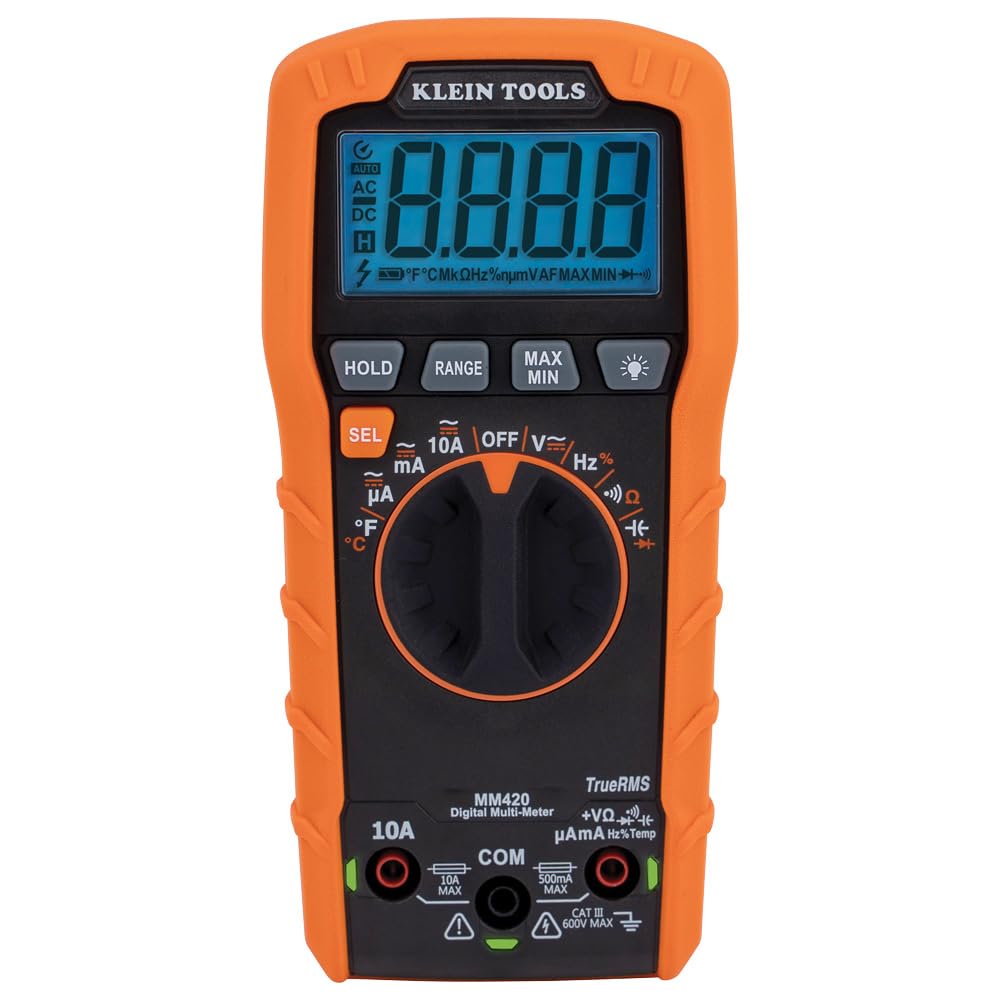
Klein Tools MM420 Auto-Ranging Multimeter
- TRMS V, resistance, and continuity
- Map each node vs the calculator model
- Budget bench/field diagnosis tool
- Electrical catalog

Ideal Industries 61-757 Clamp Meter
- 600A AC/DC TRMS branch current
- Measure current without breaking the branch
- Reconcile divider splits vs prediction
- Electrical catalog

Klein Tools CL800 Digital Clamp Meter
- 1000V class TRMS clamp
- Per-branch amps on live parallel groups
- Spot the branch that's shorted or open
- Electrical catalog

Klein Tools NCVT-3P Non-Contact Voltage Tester
- Confirm de-energized before ohms tests
- Dual-range presence check
- Prevents meter damage on in-circuit R
- Electrical catalog
As an Amazon Associate, TestTalkHQ earns from qualifying purchases. All five cards are sourced only from the affiliate CSV with verified product images.
Frequently Asked Questions
My calculated total resistance is wrong — what did I do?
Almost always a reduction-order error: reduce every parallel cluster to one equivalent first, then sum the series sections. Adding parallel resistors like series (or vice versa) is the classic mistake. Re-solve stage by stage in the Series-Parallel Calculator.
One device died but the others still work — open or short?
That's an open in a parallel branch. Parallel paths are independent, so the rest keep running. You'll read full voltage across the open element with near-zero current through it.
Everything on the circuit is dead — why?
Look for an open in the series portion feeding the network (a blown fuse, broken conductor, or open switch). Trace voltage node to node until it drops to zero across the open.
Why does my ammeter keep blowing its fuse?
You're likely connecting it across a branch instead of in series. An ammeter is low impedance — in parallel it shorts the branch. Break the branch and insert it in series, or use a clamp meter.
Is this the same as the series-parallel guide?
No. The guide teaches the topology choice and the reduction rules. This page diagnoses why bench readings disagree with a correct calculation — faults, source droop, tolerance, and meter placement.