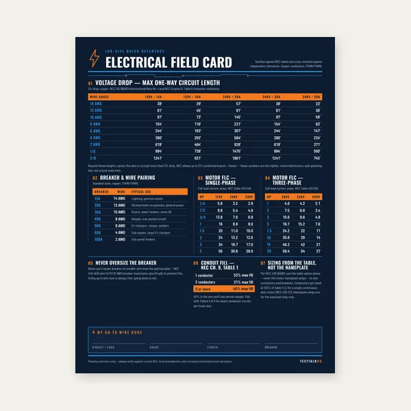
Electrical Reference Card
One page. Voltage drop lengths, breaker and wire pairing, motor FLC.
$3.99
BuyDiagnose wrong GEC size, failed rod connections, corrosion, damaged exothermic bonds, and EGC/GEC mix-ups in the field.
This is a diagnostic companion, not another sizing lesson. Start with what failed inspection or measurement, verify the electrode path safely, identify whether the problem is sizing or installation, then repair the actual defect. Use the GEC Calculator to verify Table 250.66 and the Electrode Selection Guide when the electrode system itself is wrong.
| Symptom | Likely cause | Field check | Corrective action |
|---|---|---|---|
| Inspector says GEC is undersized | Wrong Table 250.66 input, parallel sets not combined, or EGC table used | Record actual largest ungrounded service conductor and material | Recalculate from 250.66, then apply only the applicable electrode cap |
| Rod conductor moves in clamp | Loose, wrong-size, wrong-material, or non-listed clamp | De-energize; inspect listing, conductor range, corrosion, and torque instructions | Replace with a listed direct-burial connector and torque exactly as marked |
| Exothermic connection cracks or separates | Wet mold, dirty metal, wrong charge, poor fit, or impact damage | Inspect the entire weld perimeter for voids, slag, cracks, and incomplete fusion | Remove the failed connection and remake it with the listed system and procedure |
| Green/white corrosion at accessible joint | Moisture, dissimilar metals, unlisted connector, or damaged plating | Clean enough to identify base metals and connector markings | Replace compromised hardware; use listed compatible materials and required compound |
| Ground rod exists but branch fault path fails | GEC confused with EGC | Trace the branch/feeder equipment ground back to the source | Repair the EGC path per 250.122; the rod/GEC cannot clear branch faults by itself |
A common failure is assuming “6 AWG copper always works for rods” means the entire grounding electrode system can be reduced to 6 AWG. The rod cap limits the conductor required solely for a rod, pipe, or plate electrode; it does not erase sizing rules for a common conductor serving other electrodes.
Likely causes: a water-pipe clamp was used on a rod, the connector is not listed for direct burial, conductor size falls outside the marked range, copper and aluminum were mixed without an appropriate listing, or the screw was tightened by feel instead of the manufacturer specification.
Field diagnosis: after safe isolation, expose the connection without damaging the conductor. Read the connector markings. Check whether the clamp is listed for the electrode type, conductor material, conductor range, burial environment, and number of conductors. Look for a polished slip path, cracked body, stripped screw, or strands cut by overtightening.
Fix: do not shim, double-wrap, solder, or stack unapproved conductors under one screw. Replace the connector with a listed ground-rod clamp sized for the rod and GEC. Prepare the surfaces as the listing directs and torque with a calibrated tool to the published value.
An exothermic connection is not a mechanical clamp and cannot simply be “retightened.” A sound connection is permanent. Apparent looseness means the weld is incomplete, cracked, contaminated, or physically damaged.
Field diagnosis: inspect for a full, smooth weld around the intended connection; reject visible slag inclusions, deep voids, cracks, missing metal, or incomplete fusion to the rod/rebar/conductor. Verify the mold, weld-metal charge, conductor size, and electrode combination were listed together. Moisture, rust, oil, a cold mold, and a conductor that did not seat fully are common causes.
Fix: follow the manufacturer’s disposition for the failed connection. Normally that means removing the defective connection to sound material and making a new connection at an approved location with a clean, dry mold and the exact charge specified. Never place a second shot over a defective weld unless the listed system explicitly permits it.
Diagnose: distinguish harmless surface weathering from section loss or a high-resistance interface. Check for dissimilar-metal contact, water entry, damaged plating, burial of a connector not listed for burial, or aluminum installed where 250.64(A) restrictions prohibit it. A standard ohmmeter may show continuity through parallel metallic paths and cannot certify electrode resistance.
Fix: replace pitted conductors and compromised connectors rather than polishing away missing metal. Use a connector listed for every metal present and for the environment. Apply anti-oxidant compound only where the connector instructions call for it. Restore physical protection without making a connection inaccessible when accessibility is required.
The GEC connects the grounded system to the grounding electrode system and is sized from Table 250.66 using service or separately derived system conductors. The EGC runs with branch/feeder conductors, provides the low-impedance fault-current return path, and is sized from Table 250.122 using the overcurrent device.
Field diagnosis: trace both paths. The GEC should reach the electrode system. The EGC should return with the circuit conductors to the source bonding point. A continuity reading through earth, water piping, or incidental metal does not substitute for a correctly installed EGC.
Fix: use the EGC Calculator and EGC Guide for the fault-return conductor. Use the GEC pair only for the electrode connection. Correct neutral isolation and bonding at downstream panels as part of the approved design.
A perfectly sized conductor cannot fix a missing electrode. NEC 250.50 generally requires all grounding electrodes present at a building to be bonded together. A qualifying concrete-encased electrode cannot be ignored because a rod is easier to install; a qualifying metal underground water pipe electrode requires a supplemental electrode. Use the Grounding Electrode Selection Guide to audit what is present and what must be supplemented.
One page. Voltage drop lengths, breaker and wire pairing, motor FLC.
$3.99
Buy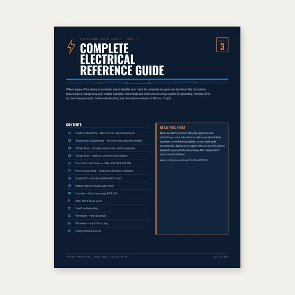
15 pages. Ampacity, corrections, voltage drop, motor circuits, conduit fill.
$12.99
Buy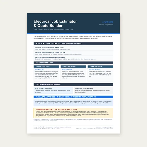
Quote electrical work and flag panel headroom before you price it.
Excel or Google Sheets. Best on a computer.
$29.00
Buy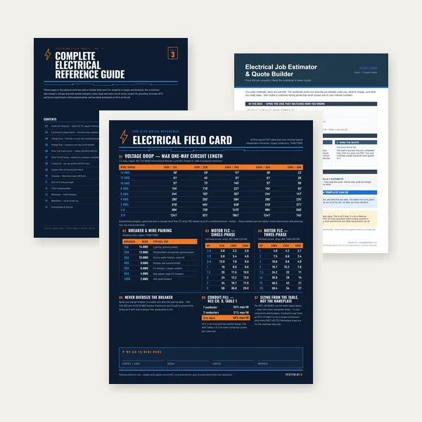
Card, 15-page guide and the estimator workbook. All six files.
Excel or Google Sheets. Best on a computer.
$34.99
$45.98 if bought separately — save $10.99
BuyCheckout opens in a new tab.
Five relevant picks from the live TestTalkHQ affiliate catalog for safe testing, termination work, and corrosion control.

Helps control oxide at listed aluminum terminations when the connector instructions require compound. It does not make an unlisted clamp acceptable.
Check Price
Useful for de-energized continuity screening and checking unexpected voltage before opening service equipment. It is not an earth-resistance tester.
Check Price
Checks current and voltage around service work without opening the circuit for every measurement. Do not confuse it with a clamp-on ground-resistance tester.
Check Price
A first-pass voltage screen at enclosures, water piping, and exposed metal before hands-on inspection. Prove the tester before and after use.
Check PriceApplies a documented clamp or lug torque instead of tightening by feel. Always use the connector manufacturer’s value and the correct socket or crowfoot correction.
Check PriceAs an Amazon Associate, TestTalkHQ earns from qualifying purchases. Catalog gaps: no ground rod, listed acorn clamp, exothermic-weld kit/mold, dedicated earth-resistance tester, or GEC-size copper conductor is present in the 311-row CSV.