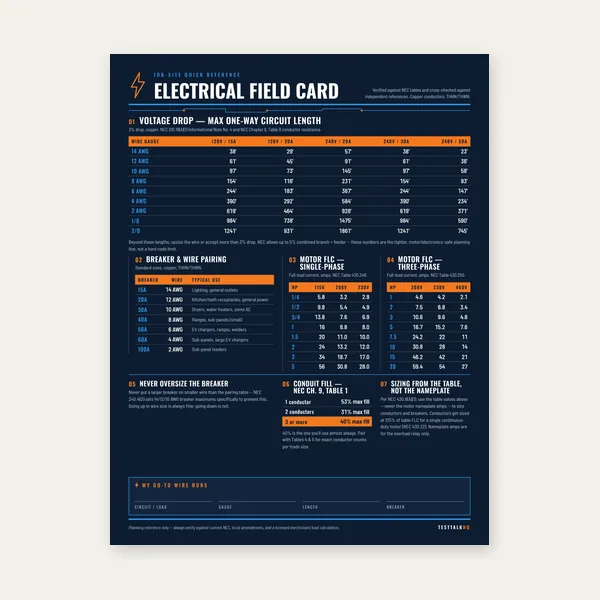
Electrical Reference Card
One page. Voltage drop lengths, breaker and wire pairing, motor FLC.
$3.99
BuyDiagnose inspector rejects, EGC/GEC table mix-ups, shared-raceway sizing errors, missed 250.122(B) upsizing, and continuity failures a calculator cannot see
Not another walkthrough of how to read Table 250.122. Pair this page with the Equipment Grounding Conductor Calculator when the lookup “should” pass and the job still fails inspection or a fault path is open. For definitions and sizing rules use the EGC Guide — this article stays on diagnosis. Keep the roles straight: the EGC is the fault-current return path bonding equipment (Table 250.122). The GEC connects the system to earth/electrodes (Table 250.66). They are not interchangeable.

Use this when an inspector red-tags the green wire, a receptacle tester shows open ground, or plan review rejects a size that “matches” the phase conductors.
| Problem | What it usually means | First fix | Next tool |
|---|---|---|---|
| Inspector rejects EGC that “matches” phase size | Sized off conductor AWG instead of the upstream OCPD rating (Table 250.122 input) | Read breaker/fuse handle; re-lookup 250.122 for that OCPD | EGC Calculator |
| Green wire sized from Table 250.66 | EGC confused with GEC — electrode table used for branch/feeder ground | Confirm job is circuit EGC (250.122) vs service electrode conductor (250.66) | Grounding vs Bonding |
| Shared conduit, multiple OCPDs, one skinny ground | EGC not sized for the largest OCPD protecting conductors in that raceway when required | List every OCPD feeding the raceway; size EGC to the largest applicable rating | EGC Guide |
| Phases upsized for voltage drop; ground still table-min | Missed 250.122(B) proportional EGC increase | Compute phase upsizing ratio; apply same ratio to Table 250.122 minimum | Voltage Drop Calculator |
| Open-ground / hot metal / receptacle fail | Bonding jumper or EGC continuity failure — paint, corrosion, missing box bond | Continuity test EGC path end-to-end; clean lugs; bond metallic boxes | Grounding vs Bonding |
| Parallel feeders, one ground pulled | 250.122(F) parallel EGC rules ignored | EGC in each set / combined circular mils per parallel rules | EGC Guide |
What it looks like: Plan or pull ticket shows a ground matching the phase conductors (or matching “what we always pull”). Calculator or table row for a different ampacity looks fine. Inspector cites undersized equipment grounding conductor against the breaker on the schedule.
Why it happens: Table 250.122 is keyed to the rating or setting of the automatic overcurrent device ahead of the equipment — not to ungrounded conductor ampacity and not to “whatever AWG is on the spool.” Crews habitually match green to black/red. That overshoots sometimes and undershoots when phase wire is smaller than the OCPD allows, or when someone used the ampacity of the wire instead of the handle rating.
Likely causes checklist:
Fixes:
What it looks like: Branch or feeder ground sized from Table 250.66 (service conductor / electrode rules), or a fat conductor to a ground rod treated as if it replaces the green wire in the raceway. Subpanel “grounded” with a local rod and no EGC back to the source. Plan review asks why Table 250.66 appears on a 60 A feeder ground.
Why the names collide: Both say “grounding.” They do different jobs with different inputs.
A #6 to a ground rod does not clear a branch-circuit fault the way a correctly sized EGC back to the panel does. Earth is a poor return path; the EGC is the intentional low-impedance path. Conceptual fork: Grounding vs Bonding Explained. Electrode sizing: GEC Calculator and GEC Guide.
Fixes:
What it looks like: Phase conductors jumped from 10 AWG to 6 AWG (or larger) for a long run. Breaker still 30 A or 60 A. Ground left at the Table 250.122 minimum for that OCPD. Plan reviewer marks 250.122(B). Field “passes” the calculator’s base row and fails the proportional increase.
Why it happens: NEC 250.122(B) requires the EGC to increase in size proportionally when ungrounded conductors are increased in size for voltage drop (or similar reasons). The base table row is only the starting minimum. Upsizing phases without adjusting the EGC is one of the most frequent plan-check hits on long feeders and shop runs.
How to diagnose:
Fixes:
What it looks like: Table size is correct. Outlet tester shows open ground. Metal box or equipment frame is hot to a known ground under fault or shows unexpected voltage. Continuity from device yoke to panel ground bar is open or high-resistance. Paint, powder coat, or corrosion under a ground lug. Missing bonding bushing / jumper at a concentric knockout. Plastic box with no ground pigtail to the device.
Why sizing tools are silent: The calculator answers “how big.” Continuity answers “is the path actually there?” An undersized wire fails math; a painted lug fails physics while the takeoff looks perfect.
Likely causes:
Fixes:
If the dispute is wire size on a branch/feeder ground → EGC / Table 250.122 (this calculator family). If the dispute is the conductor to rods, Ufer, or water-pipe electrodes at the service → GEC / Table 250.66. If size is correct but metal is open or hot → bonding continuity, not another table row. Conceptual fork and why earth is not the fault return: Grounding vs Bonding Explained.
One page. Voltage drop lengths, breaker and wire pairing, motor FLC.
$3.99
Buy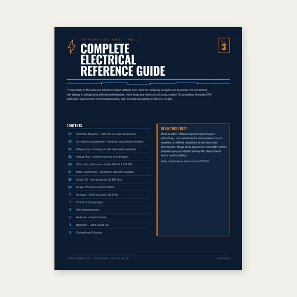
15 pages. Ampacity, corrections, voltage drop, motor circuits, conduit fill.
$12.99
Buy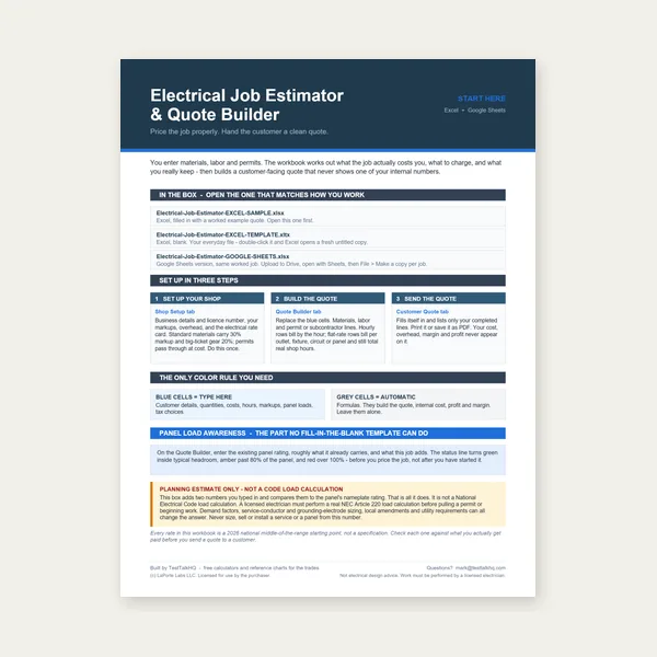
Quote electrical work and flag panel headroom before you price it.
Excel or Google Sheets. Best on a computer.
$29.00
Buy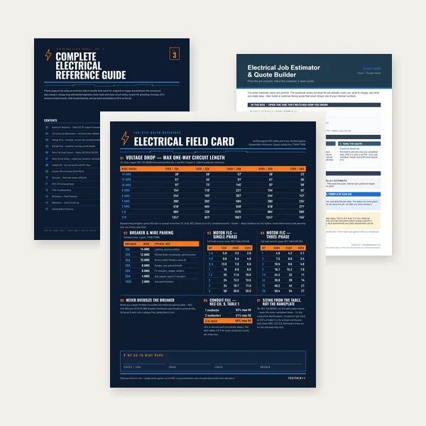
Card, 15-page guide and the estimator workbook. All six files.
Excel or Google Sheets. Best on a computer.
$34.99
$45.98 if bought separately — save $10.99
BuyCheckout opens in a new tab.
Six electrical picks from the TestTalkHQ affiliate catalog — meters, outlet tester, stripper, anti-oxidant, breaker, and breaker finder for OCPD verification

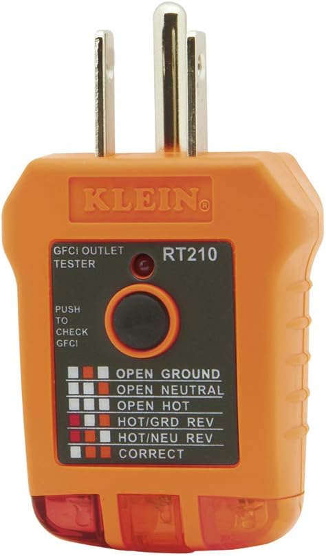



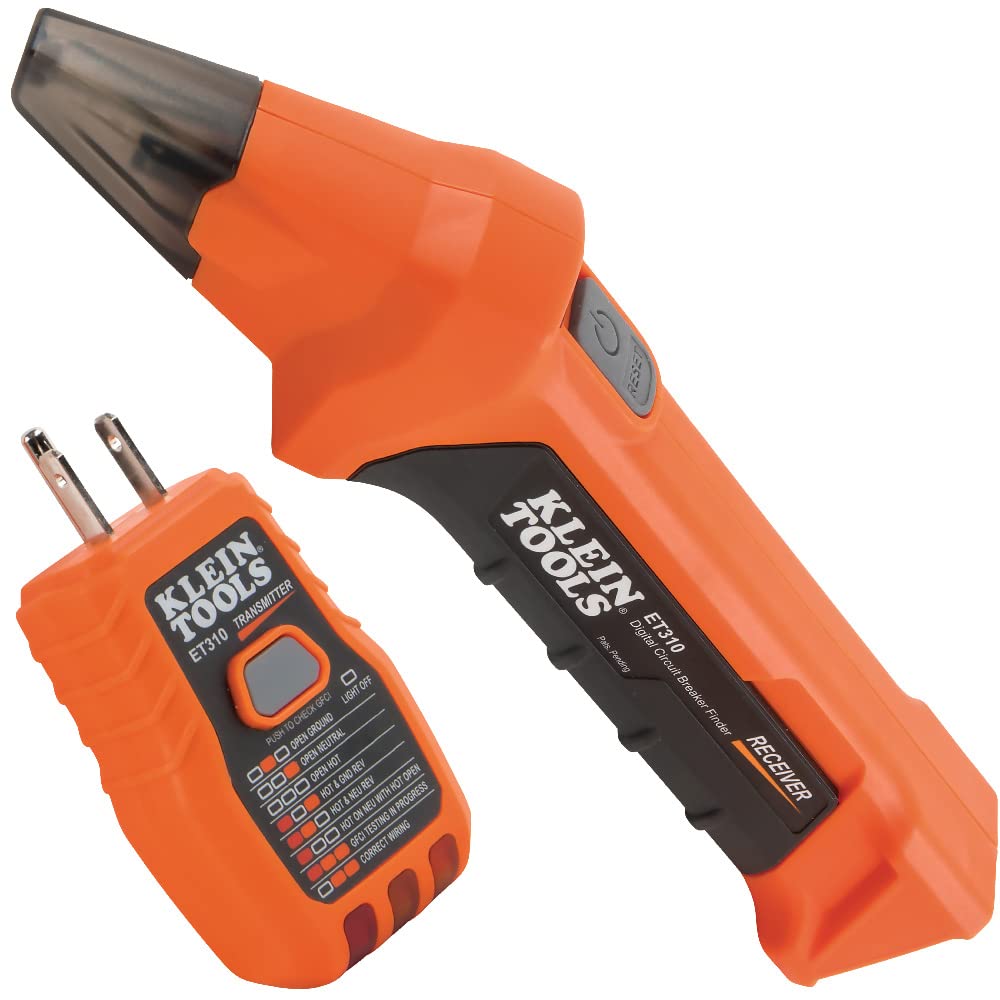
As an Amazon Associate, TestTalkHQ earns from qualifying purchases. Always follow manufacturer torque and listing requirements — compound is not a substitute for the correct connector or a continuous EGC path.
Table 250.122 sizes the EGC from the overcurrent device rating, not from phase AWG. Matching black and green is convenient only when that size meets or exceeds the table for the actual breaker.
No for branch and feeder EGCs. Table 250.66 is for the grounding electrode conductor to earth. Use Table 250.122 for the EGC. Mixing them is one of the most common grounding mistakes on plans.
Often yes. NEC 250.122(B) requires a proportional increase when ungrounded conductors are increased in size. Re-check after every upsizing change order.
Continuity and bonding: painted lugs, missing jumpers, cut bare grounds, corroded Al terminations. A calculator cannot see those — meter them.
No. Fault current needs a low-impedance path back to the source. A local rod is not a substitute for the equipment grounding conductor (or qualifying raceway) back to the supply. See Grounding vs Bonding.
Use the EGC Calculator or the table walkthrough in the EGC Guide. For electrode conductors use the GEC Calculator instead.