
The calculation said 20 SCFM. The compressor is running 80 percent of the time and the gauge sags every cycle. Somewhere between the arithmetic and the machine, air is going missing, and it is almost always one of six things. This is the order to check them in, with the measurement that settles each one, because guessing at this in the wrong order costs days.
First, measure the gap before you chase it
Do not start replacing parts. Start by establishing how big the discrepancy actually is, because the size of the gap points at the cause.
The cheapest real measurement on a reciprocating compressor is the load/unload ratio. Run the machine at its normal rate and time how long the compressor spends loaded versus unloaded over ten minutes or so:
A unit rated 15 SCFM that is loaded 8 minutes in every 10 is delivering about 12 SCFM into the system. Compare that with your calculated figure. Then repeat the test with the machine switched off and every cylinder at rest — anything the compressor still has to make up is leakage.
The pressure-decay alternative
If the compressor cannot be watched easily, pump the system to working pressure, shut the compressor off, close nothing else, and time the decay. With a known receiver and pipe volume, the ideal gas law gives the leak rate directly:
A 60 gallon receiver is 8.02 cubic feet. If it falls from 120 to 100 psig in 4 minutes with everything idle, that is 8.02 × 20 / 14.7 / 4 = 2.7 SCFM of leakage — before counting the pipe volume, which makes it worse. On a machine calculated at 20 SCFM, that is more than an eighth of total demand before the machine has even started.
Cause 1 — leaks, which are almost always the answer
If the gap is large and present when the machine is idle, stop reading and fix leaks. Nothing else on this list competes on size. Leak flow through a fixed opening scales with absolute pressure, so a system run at 120 psig leaks about 42 percent more than the same holes at 80 psig.
Where they actually are, in rough order of frequency: quick-connect couplers, push-to-connect fittings that have been disturbed, cylinder rod seals on old actuators, valve exhaust ports that hiss continuously rather than only during a stroke, thread sealant that was never applied on a repair, and drain valves left cracked open.
A leak that is not a leak
A valve exhaust that hisses only while a cylinder is holding position is often an internal seal in the valve or the cylinder, not an external leak. It shows up in the idle test only if the machine is left pressurised mid-sequence, which is exactly why you should run the idle test with the machine parked in its normal rest state and again mid-cycle if you can do it safely.
Cause 2 — something is consuming air that is not in your schedule
This is the second most common, and the most embarrassing when found. Continuous consumers dwarf intermittent cylinders and they rarely make it onto the cylinder schedule because nobody thinks of them as actuators.
- Blow-off nozzles and part ejection air. An open 1/8 inch tube at 80 psig is a large continuous consumer — frequently larger than every cylinder on the machine combined. Engineered nozzles and timing the blast to the part cut this dramatically.
- Air amplifiers, vortex coolers, and cabinet coolers. Continuous, and sized in tens of SCFM.
- Vacuum generators. A venturi vacuum cup draws air the whole time it holds the part, not just when it picks up. On a machine with several cups this is often the single biggest line item.
- Air-piloted valves and air logic. Small individually, real in quantity.
- Purge air on sensors and enclosures. Set once, forgotten forever.
Gear that decides whether the numbers hold
Most of the gap between a calculated SCFM figure and the one a flow meter shows lives in these four items.
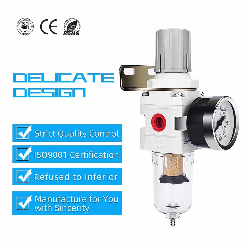
Filter / Regulator Combo
- Sets the station pressure your calculation assumed
- Keeps condensate out of cylinder seals
- Mounts at the machine, where regulation belongs

Regulator & Flow Control 0-150 PSI
- Run the lowest pressure that still makes the force
- Gauge makes the assumption checkable
- Station control instead of raising the whole header
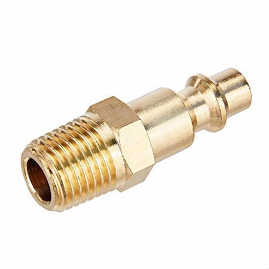
Quick Connect Brass Coupler Kit
- Undersized couplers starve a fast-cycling cylinder
- Same fitting standard at every station
- Brass resists the corrosion that shrinks bore
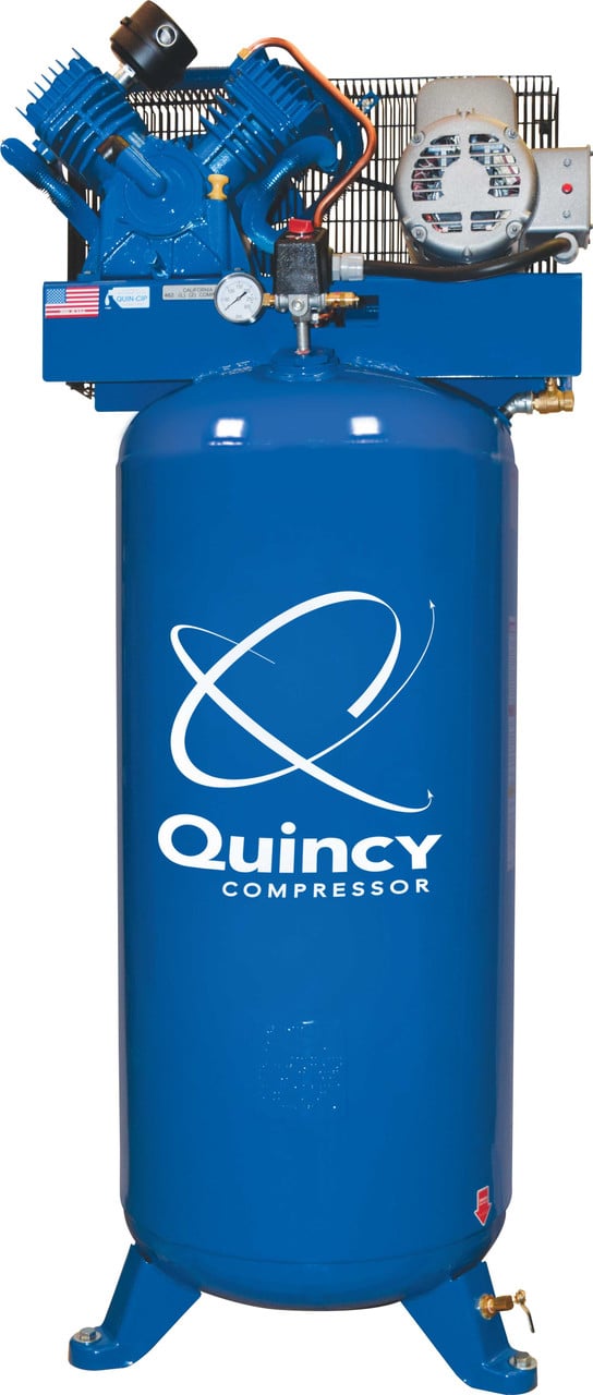
Quincy QT-54 5 HP 60-Gallon
- Continuous-duty supply for a continuously cycling cell
- Receiver volume absorbs per-cycle peaks
- Suits a small cell running several cylinders
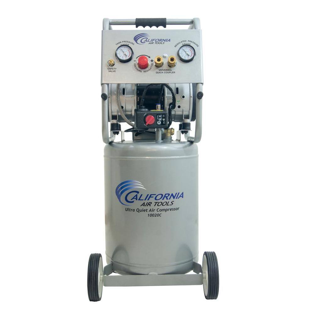
California Air Tools 10020CAD
- Low-SCFM cells running beside people all day
- Auto drain keeps water out of the cylinder feed
- Oil-free, so nothing carries over onto the work
As an Amazon Associate, TestTalkHQ earns from qualifying purchases. Prices and availability can change.
Cause 3 — the pressure is not what you calculated at
Consumption scales with absolute pressure, so a station running 30 psi above the figure you used is consuming proportionally more air for exactly the same work. At 80 psig assumed and 110 psig actual, the compression ratio goes from 6.44 to 8.48 — 32 percent more air, with no change to the machine.
Check the regulator actually feeding the cylinders while the machine is running, not the header gauge and not the setting on the drawing. Regulators drift, get adjusted during a breakdown at 2am, and sometimes get bypassed entirely.
Cause 4 — the cycle rate is higher than you think
Consumption is linear in cycle rate, so this is a pure multiplier on everything. Two versions of the same mistake:
- Counting strokes as cycles. A cycle is extend plus retract. A machine advertising 40 moves a minute is doing 20 cycles a minute. If your schedule says 40, every figure in it is double.
- Using the design rate instead of the real one. Machines get sped up. Check with a stopwatch over several minutes; do not trust the HMI counter or the original specification.
Re-run the air consumption calculator with the measured rate and measured pressure before concluding anything is wrong with the machine. A surprising share of “excess consumption” cases close right here.
Cause 5 — slow cylinders, which are a different problem entirely
If the actual complaint is speed rather than consumption, the cause is restriction, and no amount of compressor is going to help. Check in this order, because it is roughly the order of likelihood:
- The exhaust path. A blocked muffler is the classic. Pull it off and cycle the machine — if it suddenly moves properly, you have found it. Mufflers load up with compressor oil and shop dust and they are almost never on a maintenance schedule.
- Meter-out flow controls. Somebody slowed a cylinder deliberately, possibly years ago and for a reason that no longer exists.
- Valve Cv too small for the bore. A large cylinder on a small valve is a permanent restriction. This is a sizing error and it needs a bigger valve, not more pressure.
- Tube bore and fittings. Push-to-connect fittings with a smaller bore than the tube quietly throttle the line; so does a long run of small tube to a large cylinder.
- Local pressure collapse during the stroke. If the gauge at the machine dives while the cylinder moves, this is a storage and pipe problem, not a valve problem.
Cause 6 — the tubing is the consumer
On short-stroke cylinders, the air used to fill the port tubing every cycle can exceed the air used to move the piston. A 1 inch bore with a 1 inch stroke fed through 20 feet of 1/4 inch tube spends more on the tube than the cylinder, every cycle, forever.
This shows up as a machine whose measured consumption is far above a calculation that ignored tubing — and it is invisible to leak detection because nothing is actually leaking. The fix is layout, not parts: move the valve to the cylinder, or manifold the valves at the actuators rather than in a cabinet at the other end of the machine.
The short diagnostic order
- Measure total demand and idle leakage with the load/unload or decay test.
- If idle leakage is significant, fix that first and re-measure. Everything else is noise until it is done.
- Walk the machine for unscheduled continuous consumers.
- Verify actual regulator pressure and actual cycle rate, then re-run the calculation.
- Only now compare remaining gap against the cylinder schedule, checking tubing volume on short-stroke stations.
- Treat speed complaints separately, starting at the exhaust.