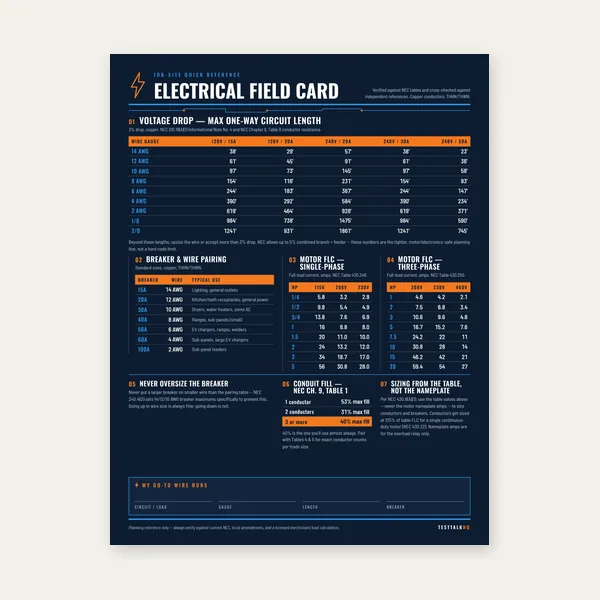
Electrical Reference Card
One page. Voltage drop lengths, breaker and wire pairing, motor FLC.
$3.99
BuyNEC Table 250.122 — what the EGC does, how it differs from the GEC, and when to upsize.
The equipment grounding conductor is the green or bare wire in your cables and raceways — not the wire to the ground rod. Use the Equipment Grounding Conductor Calculator for instant Table 250.122 results, or read the full guide below.

The equipment grounding conductor (EGC) bonds metal parts of electrical equipment together and connects them to the grounded conductor at the source. Its purpose is not to dump electricity into the earth — that is a common misconception that confuses EGC with the grounding electrode conductor (GEC). When a hot wire touches a metal box or appliance frame, the EGC provides a low-impedance path for fault current to return to the transformer or panel so the breaker or fuse opens quickly. Without that return path, the metal shell can sit energized at line voltage while the breaker stays closed.
Under normal conditions the EGC carries no load current. Under a ground fault it may carry substantial current — but only long enough for the overcurrent device to clear the fault. That is why Table 250.122 keys off the breaker or fuse rating ahead of the equipment: the EGC must handle the let-through energy associated with that device opening, not the steady-state ampacity of the phase conductors.
Both conductors have "ground" in the name. They are not interchangeable, and they are sized from different NEC tables using different inputs.
Equipment grounding conductor (EGC) — runs with circuit conductors; sized from Table 250.122 based on overcurrent device rating; provides fault return to the source; found as the bare wire in Romex, the green wire in conduit, or the grounding bus in a panel.
Grounding electrode conductor (GEC) — connects the grounded service neutral to grounding electrodes (rods, Ufer, water pipe bonds at the service); sized from Table 250.66 based on largest ungrounded service conductor; stabilizes system voltage relative to earth; typically terminates at the main bonding jumper and electrode system, not at each receptacle.
Simple analogy: the EGC is the emergency exit route that gets people (fault current) back to the building entrance (panel/source) so the alarm (breaker) triggers. The GEC is the foundation anchor that ties the building to the ground — important for the whole structure, but not the path a branch-circuit fault uses to clear. Running a #6 to a ground rod does not replace a #10 EGC in a 60-amp feeder. Using Table 250.66 to size the green wire in a branch circuit is equally wrong. Read the GEC Sizing Guide and use the GEC Calculator for electrode conductor work at the service.
The left column lists the rating or setting of the automatic overcurrent device in the circuit ahead of the equipment, conduit, or cable — expressed as a maximum value. Find the row that equals or exceeds your breaker or fuse rating, then read the copper or aluminum EGC column.
| OCPD rating (A) | Copper EGC | Aluminum EGC |
|---|---|---|
| 15 or less | 14 AWG | 12 AWG |
| 20 | 12 AWG | 10 AWG |
| 60 | 10 AWG | 8 AWG |
| 100 | 8 AWG | 6 AWG |
| 200 | 6 AWG | 4 AWG |
| 300 | 4 AWG | 2 AWG |
| 400 | 3 AWG | 1 AWG |
| 500 | 2 AWG | 1/0 AWG |
| 600 | 1/0 AWG | 2/0 AWG |
| 800 | 2/0 AWG | 3/0 AWG |
| 1000 | 3/0 AWG | 4/0 AWG |
| 1200 | 4/0 AWG | 250 kcmil |
Overcurrent device: 60-amp two-pole breaker. Table row: 60 → 10 AWG copper EGC (or 8 AWG aluminum). Phase conductors might be 6 AWG THHN — larger than the EGC — and that is normal. The EGC is not sized to match phase wire area; it is sized to the breaker.
Overcurrent device: 20-amp breaker. Table row: 20 → 12 AWG copper EGC. Standard 12/2 NM-B includes a 12 AWG bare ground — correct for 20 amps. On 14/2 NM-B (15-amp circuit), the 14 AWG ground satisfies the 15-amp row.
When ungrounded conductors are increased in size to reduce voltage drop, the EGC must increase proportionally. Example: a 30-amp circuit normally uses 10 AWG phase and 10 AWG EGC from the 60-amp row. If phase conductors are upsized to 8 AWG for voltage drop while the breaker remains 30 amp, the EGC may remain 10 AWG because the table minimum still governs — but when upsizing is significant relative to the standard ampacity for that circuit size, apply the proportional increase stated in 250.122(B). Document both the OCPD rating and any upsizing on the plan.
Where phase conductors are run in parallel, EGCs must be run in parallel and sized per 250.122(F) based on the combined circular mil area. You cannot pull one 10 AWG ground for two parallel sets of 500 kcmil feeders — the parallel EGC rules apply in addition to the table minimum per ungrounded conductor set.
Motor branch circuits, instant-start or capacitor equipment, and certain tap conductors reference Table 250.122 but may include additional bonding requirements in Article 430 or 240. Always read the complete article for the equipment type — the table gives the baseline minimum.
When the table lookup looks right but the job still fails, use the diagnostic Equipment Grounding Conductor Troubleshooting guide — wrong OCPD basis, EGC/GEC table mix-ups, shared-raceway sizing, missed 250.122(B), and continuity failures. For the grounding-vs-bonding conceptual fork, read Grounding vs Bonding Explained.
Sizing EGC from phase conductor size instead of breaker rating. Pulling #8 AWG ground because the phase is #8, on a 100-amp breaker, when the table requires #8 copper minimum anyway — but on a 60-amp breaker with #6 phase, the EGC minimum is still #10, not #6.
Confusing EGC with GEC. Connecting a subpanel ground bar only to a local ground rod without a four-wire feeder ground back to the main panel violates the fault return path. Electrode connections belong at the service; EGCs return to the source.
Ignoring 250.122(B) after voltage-drop upsizing. Plans show #2 AWG phase for a 100-amp breaker but still call for #8 ground without noting proportional increase — plan reviewers catch this when conductor upsizing ratio exceeds the table baseline.
Undersized EGC in flex and MC assemblies. Using cord caps or whips with a ground smaller than Table 250.122 for the supplied overcurrent protection — the assembly ground must meet the table for the branch OCPD.
Pair EGC work with the Circuit Breaker Sizing Calculator to confirm OCPD rating, Grounding vs Bonding Explained for system-level context, and Wire Ampacity & Derating when phase conductors are upsized.
Yes — Table 250.122 lists 10 AWG copper (or 8 AWG aluminum) for overcurrent devices not exceeding 60 amps. That applies regardless of whether phase conductors are #6, #4, or larger, unless parallel EGC rules or 250.122(B) upsizing require more.
Always. The table states minimum size. Many installers match EGC to phase conductor size for convenience in pulling and terminations — that is fine when it exceeds the minimum. It is not fine when the installed EGC is smaller than the table.
Yes. In NM-B cable the bare copper conductor is the equipment grounding conductor. Verify that its size meets Table 250.122 for the breaker protecting that circuit — 14/2 with 14 AWG ground for 15 amps, 12/2 with 12 AWG ground for 20 amps.
At the service equipment, the main bonding jumper connects neutral, enclosure, and GEC to the electrode system. Branch and feeder EGCs terminate on the ground bus and return fault current to the source through the grounded conductor — not through the ground rod. Size the GEC separately with the GEC Calculator.
One page. Voltage drop lengths, breaker and wire pairing, motor FLC.
$3.99
Buy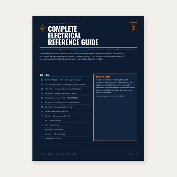
15 pages. Ampacity, corrections, voltage drop, motor circuits, conduit fill.
$12.99
Buy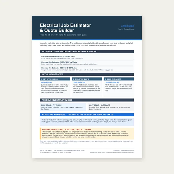
Quote electrical work and flag panel headroom before you price it.
Excel or Google Sheets. Best on a computer.
$29.00
Buy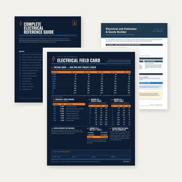
Card, 15-page guide and the estimator workbook. All six files.
Excel or Google Sheets. Best on a computer.
$34.99
$45.98 if bought separately — save $10.99
BuyCheckout opens in a new tab.
Breakers, strippers, and torque tools for EGC terminations

Confirm the overcurrent device rating on the handle before Table 250.122 lookup — a mismatched breaker label and schedule entry is how EGC mistakes start. QO breakers are the reference point for countless residential panels.
Check Price
Most EGC work in residential panels falls in the 10–14 AWG range this tool covers. Consistent strip length at ground bars prevents loose strands and failed torque connections.
Check Price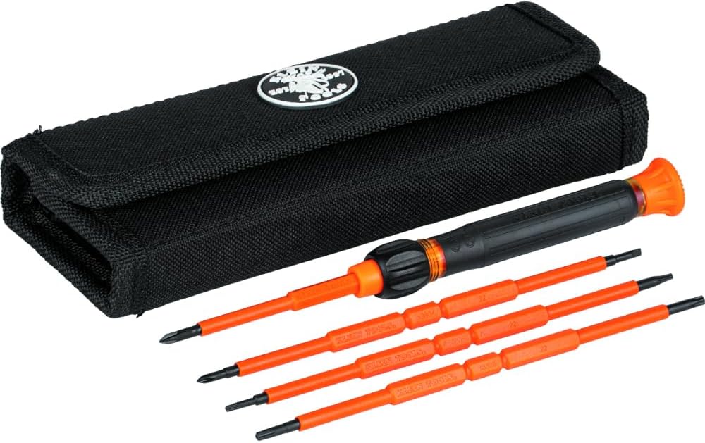
Ground bar and lug torque specs exist because under-torqued EGC terminations fail under fault current. A click-style wrench in the 40–300 ft-lb range covers panel work where EGCs land.
Check PriceAs an Amazon Associate, TestTalkHQ earns from qualifying purchases.
Phase conductors are sized for ampacity, voltage drop, and continuous load per Articles 310 and 210. The EGC is sized for fault clearing — the available fault current and the time the overcurrent device takes to open. The breaker rating is the best single variable tying EGC size to that duty. Using conductor size would oversize EGC on long voltage-drop runs and undersize it when phase conductors are smaller than the breaker allows (within 240.4(B) and tap rules). The table keeps branch and feeder EGC rules consistent across installations.
A ground fault is not "electricity going to ground" in the sense of a ground rod. Fault current flows from the source, through the fault to metal equipment, along the EGC back to the panel, and through the grounded conductor (neutral) back to the transformer. Earth is a poor conductor; the EGC is intentionally low impedance. That is why bonding and EGC continuity matter more than rod resistance for clearing branch faults — and why confusing EGC with GEC leads to dangerous open fault paths at subpanels.
When you upsize branch or feeder conductors for voltage drop, calculate the ratio of installed phase area to the minimum phase size for that circuit ampacity, then apply the same ratio to the Table 250.122 EGC minimum. If the table gives 10 AWG for a 60-amp breaker and you upsize phases enough that the code requires a proportional EGC increase, the installed ground may need to jump from 10 AWG to 8 AWG or larger. Note the upsizing on as-built drawings — inspectors compare OCPD, phase, and EGC sizes together.
Read the breaker handle or fuse label, look up Table 250.122, compare to the ground wire gauge printed on cable jacket or measured at the ground bar. For conduit runs, verify the pulled ground matches the table for the breaker in the panel — not the phase wire size on the spool. At the service, confirm GEC sizing separately at Table 250.66. Both checks must pass; one does not substitute for the other.