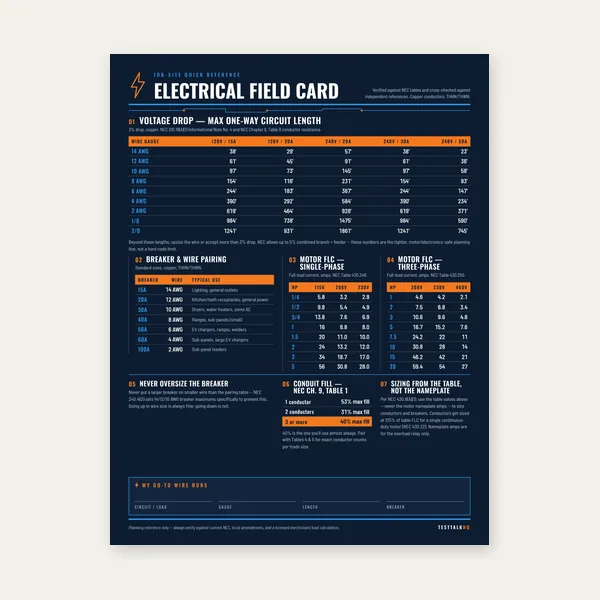
Electrical Reference Card
One page. Voltage drop lengths, breaker and wire pairing, motor FLC.
$3.99
BuyAvailable fault current, AIC ratings, NEC 110.9, and when a formal study beats a back-of-envelope estimate.
Every breaker, panel, and disconnect at a location must be able to interrupt the maximum current that can appear there during a fault. That maximum is available fault current — and the equipment rating that must meet or exceed it is AIC (ampere interrupting capacity).
Use the Short Circuit / Fault Current Calculator for point-to-point estimates from transformer kVA and feeder length, or read the full guide below.

Available fault current (short-circuit current, bolted-fault current) is the maximum current the electrical system can deliver to a point where a solid fault occurs — phase-to-phase or phase-to-ground. It is not the normal load current on the circuit. It is the current that flows when impedance is essentially zero at the fault location, limited only by the impedance of everything upstream: utility transformer, service entrance, transformers, conductors, and connections.
That number drives equipment selection. NEC 110.9 states that equipment intended to interrupt current at fault levels shall have an interrupting rating sufficient for the current that must be interrupted. If a 10k AIC panel is installed where 22,000 amps are available, the panel and its breakers are not listed for the duty they may face. During a real fault, an undersized device may weld shut, explode, or eject hot gases instead of opening cleanly — endangering workers and equipment. Available fault current is therefore a safety parameter, not an academic one.
Fault current increases when the source is closer (larger transformer, lower impedance), when conductors are larger and shorter (less impedance between source and point), and when the utility stiffens (new transformer, upgraded service). It decreases with distance, smaller wire, and higher system impedance. Every renovation that upsizes service equipment or adds a larger transformer can push available fault current above the interrupting rating of existing downstream gear.
AIC — ampere interrupting capacity — is the maximum fault current a protective device or assembly can safely interrupt at its rated voltage. You will also see IR (interrupting rating), AIR (available interrupting rating), or values expressed in kAIC (thousands of amps interrupting capacity). A marking of 22k AIC @ 240V means the device can interrupt faults up to 22,000 amps at that voltage.
Look on the breaker face, side label, or packaging. Molded-case breakers typically show AIC in kA at specific voltages — for example, 10k @ 120/240V or 22k @ 240V. The rating varies by breaker series, frame size, and voltage. A 20A QO breaker and a 200A QO main may have different interrupting ratings even in the same product family — always read the specific device label.
The panel label inside the door lists the assembly short-circuit current rating (SCCR) or AIC at the system voltage. Branch breakers installed in the panel must be compatible with that rating — you cannot assume every breaker in the catalog meets the panel's available fault level. When replacing a panel, match or exceed the calculated available fault current at the line terminals.
Fused switches, safety switches, contactors with integral OCPD, and MCC buckets all carry interrupting or withstand ratings on their nameplates. Motor starters and contactors have separate short-circuit ratings — the contactor alone does not clear a fault; the branch overcurrent device does.
Overcurrent devices are tested to interrupt specific fault levels. Below that level, the breaker operates as designed — contacts open, arc is extinguished, energy is contained. Above that level, the internal arc may not be controlled. Witness marks include housing breach, contact welding, continued arcing, and fire. Workers standing in front of a panel during a fault on undersized equipment face arc-flash and blast hazards beyond what the gear was designed to contain.
Undersized AIC is a code violation under NEC 110.9 and a liability exposure. It often surfaces during service upgrades: the utility installs a larger transformer, available fault current jumps from 14kA to 28kA, and the existing 200A main panel rated 22kA is no longer adequate. Inspectors who request fault-current documentation will flag the mismatch. Corrective action is replacing the panel or main device with a higher AIC rating, or engineering a listed series-rated combination — not ignoring the calculation.
The point-to-point method estimates fault current in two stages without modeling the entire utility grid.
Step 1 — Transformer secondary. From the transformer nameplate kVA and % impedance (%Z), available current at the secondary terminals is approximated by:
Isc = (kVA × 1,000) ÷ (√3 × VLL × (%Z ÷ 100))
where VLL is line-to-line secondary voltage in volts and %Z is the nameplate impedance (e.g., 3 for 3%). Equivalently, with voltage in kV: Isc = (kVA × 100) ÷ (√3 × kV × %Z).
150 kVA, 208V three-phase secondary, 3% impedance:
Isc = (150 × 1,000) ÷ (1.732 × 208 × 0.03) = 150,000 ÷ 10.81 ≈ 13,900 A at the transformer terminals.
Step 2 — Downstream point (f-factor). Feeder conductors add impedance that reduces fault current at the far end. The f-factor method uses:
f = (1.73 × L × Isc) ÷ (C × n × VLL)
where L is one-way conductor length in feet, C is a constant from standard tables for the wire size and material, n is the number of conductors per phase in parallel, and VLL is line-to-line voltage. Then M = 1 ÷ (1 + f) and Iat point = Isc × M.
Using C = 23,700 for 4/0 copper, one conductor per phase, L = 50 ft:
f = (1.73 × 50 × 13,900) ÷ (23,700 × 1 × 208) ≈ 0.24
M = 1 ÷ 1.24 ≈ 0.81 → I ≈ 11,200 A at the end of the run — meaningfully lower than the 13,900 A at the transformer, confirming feeder derating is applied.
Run your own numbers in the Short Circuit / Fault Current Calculator. For branch circuit overcurrent sizing (separate from interrupting rating), use the Circuit Breaker Sizing Calculator. Document panel layouts with the Panel Schedule Calculator.
A rough point-to-point estimate is often enough when:
A licensed engineer and software study (SKM, EasyPower, ETAP, etc.) is appropriate when:
Point-to-point ignores motor contribution, capacitor banks, and utility impedance details. It is a conservative starting point for feeder derating from a transformer — not a replacement for a full system model when the stakes and code require one.
The utility replaces a pole transformer with a larger kVA unit or lower impedance. Available fault current at the service entrance rises. Existing meter mains, panels, and branch devices that were marginally adequate may now violate NEC 110.9. Any utility work notification should trigger an AIC review of the entire service and main distribution — not just a check that the service conductors are large enough for load.
A 100A to 200A service upgrade often installs larger service entrance conductors and a new main breaker — but if the interior panelboard remains an older 10k or 18k AIC unit, the panel itself may be undersized for the new available fault current even when the main breaker is new. Read the panel label SCCR, not only the main breaker AIC.
A new 150 kVA or 300 kVA dry-type transformer for a machine branch creates a new source of fault current on the secondary. Secondary main and branch breakers must be rated for the secondary fault level, which can be surprisingly high on a stiff primary. Size the transformer with the Transformer Sizing Calculator, then verify secondary AIC before ordering the disconnect and panel.
Fault current is highest at the transformer and lowest at the end of a long, small feeder. A branch panel at the end of a long run may see lower fault current than a panel tapped directly at the service — but equipment at the service equipment itself sees the highest value in the system. Always evaluate AIC at the specific point where each device sits, not only at the load end.
No. Load current is what the connected equipment draws during normal operation. Available fault current is the prospective current during a dead short — typically thousands to tens of thousands of amps on commercial systems. Breaker amp rating (20A, 200A) addresses continuous load; AIC rating addresses fault interruption.
No. Voltage drop addresses steady-state performance and conductor sizing for load. Fault current addresses equipment interrupting ratings. You need both on feeders — use the voltage drop calculator for VD and this guide or calculator for AIC.
Only with listed combinations documented per NEC 240.86 — upstream specified breaker plus downstream devices tested as a pair. You cannot arbitrarily pair a high-AIC main with low-AIC branches without manufacturer data. When in doubt, specify fully rated equipment.
NEC 110.9 requires interrupting rating not less than available fault current for equipment intended to interrupt fault current. Related: NEC 110.10 on circuit impedance, NEC 240.86 on series ratings, and product standards (UL 489, UL 67) that define testing for listed equipment.
One page. Voltage drop lengths, breaker and wire pairing, motor FLC.
$3.99
Buy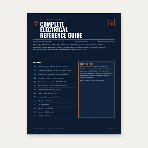
15 pages. Ampacity, corrections, voltage drop, motor circuits, conduit fill.
$12.99
Buy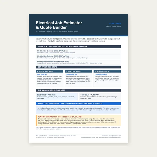
Quote electrical work and flag panel headroom before you price it.
Excel or Google Sheets. Best on a computer.
$29.00
Buy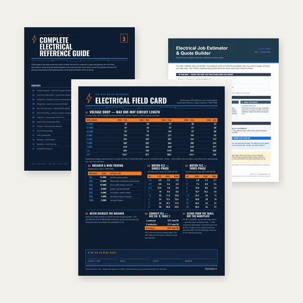
Card, 15-page guide and the estimator workbook. All six files.
Excel or Google Sheets. Best on a computer.
$34.99
$45.98 if bought separately — save $10.99
BuyCheckout opens in a new tab.
Clamp meters for inrush and fault-level verification, multimeters for safe dead checks, and listed panels with documented AIC

When validating upgrades, a true-RMS clamp meter on the service helps confirm operating conditions and troubleshoot parallel paths during AIC reviews. CAT IV 1000V rating suits main distribution equipment where fault-current verification work happens — always follow safe work practices and never depend on a field meter alone for formal fault studies.
Check Price
Before opening a panel to read AIC labels or swap breakers, verify the equipment is de-energized. The Fluke 117 combines non-contact voltage detection with standard DMM functions — standard practice before any work where available fault current could be present on live bus.
Check Price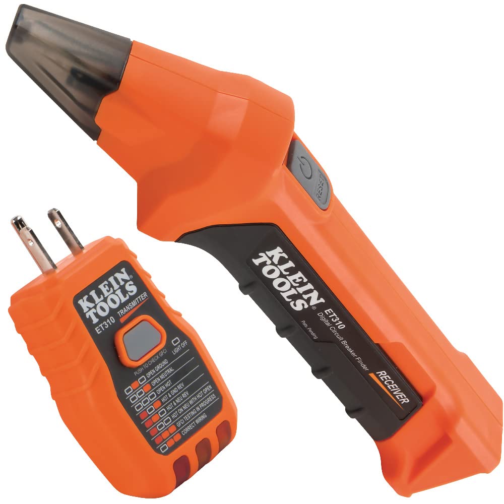
During panel replacements driven by AIC upgrades, tracing which branch lands on which breaker speeds safe shutdown and labeling. The ET310 pairs transmitter and receiver for outlet-to-breaker identification — useful when replacing an entire underrated panelboard.
Check PriceAs an Amazon Associate, TestTalkHQ earns from qualifying purchases.
A 20-amp breaker safely carries 20 amps of load current indefinitely (subject to 80% continuous rules). It is not tested to interrupt 20 amps of fault — it is tested to interrupt thousands of amps up to its AIC limit. The amp rating and the kAIC rating answer different questions. NEC 110.9 ensures the second question is answered for every point where a device must clear a fault. Equipment that only "fits" physically in a panel slot but lacks adequate interrupting rating for that location's available fault current is not compliant — even if it has carried load without tripping for years.
Available fault current at your service is set largely by the utility transformer and conductor impedance from the pole or pad to your meter. Closer transformers, larger transformers, and lower-impedance designs all increase the value. On-site transformers add another source on their secondaries — secondary fault current can exceed what branch circuits intuitively suggest for a "small" 150 kVA unit. Any project that changes service size, adds parallel feeds, or installs new transformation should include an AIC check before equipment is ordered. Catching an underrated panel at rough-in is cheap; catching it after energization is expensive and dangerous.
Panel schedules, one-line diagrams, and permit submittals increasingly note available fault current and equipment SCCR. When you build a schedule with the Panel Schedule Calculator, add a note on the drawing for calculated available fault current and verified panel AIC. Inspectors in many jurisdictions compare those values. Matching documentation to calc output reduces rework and supports safer equipment selection on commercial tenant improvements and service upgrades.
Breaker sizing per NEC 210.20 and 240.6 addresses normal load and conductor protection — the Circuit Breaker Sizing Calculator handles that path. Transformer sizing per NEC 450 addresses kVA and secondary overcurrent — the Transformer Sizing Calculator and Transformer Sizing Guide cover that layer. AIC verification is the third leg: after you know the transformer and breakers are sized for load, confirm every interrupting device can handle the fault energy available at its terminals. Skipping the third leg leaves a compliant-looking design that still fails NEC 110.9.