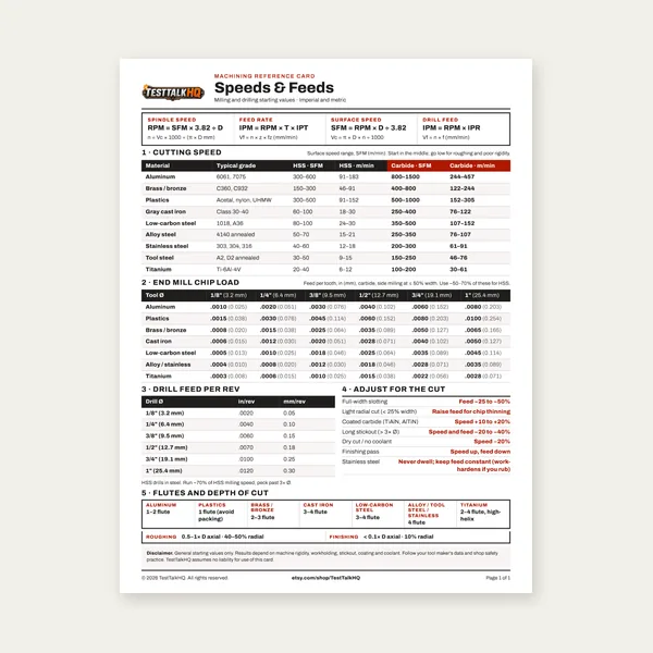
Machining Speeds & Feeds Card
One page. Speeds, chip load and drill feed, imperial and metric.
$3.99
BuySet up right, run the correct speed and feed, and stop breaking parting blades for good.
Parting off is one of the most demanding operations on a manual lathe — a narrow blade, high cutting forces, and zero margin for setup error. This guide covers blade selection, tool height, speed and feed, cutting fluid, and how to fix the problems that break blades and ruin parts.
Use the Parting & Cutoff Speed Calculator for exact RPM and feed numbers on your material and diameter.

Parting off — also called cutoff — is a single-point lathe operation where a narrow blade cuts straight into the workpiece until the part separates. Unlike turning, where the tool cuts along the surface with generous side support, parting drives a thin blade into the end of the stock and pushes through to center. The blade has minimal cross-section, maximum overhang, and the cutting zone is concentrated in a very small area. That combination makes parting fundamentally different from every other lathe operation.
Sawing achieves the same end result — separating a part from bar stock — but with a different tool and setup. A bandsaw or cold saw cuts from outside the workpiece with the stock held stationary. Parting cuts from inside the chuck with the workpiece rotating. The advantage of parting on the lathe is that the finished face is square to the spindle axis and you never re-chuck the part. The disadvantage is that everything about the setup — tool height, rigidity, speed, feed, and fluid — must be correct or the blade pays the price.
Parting is unforgiving because there is no buffer. In turning, a dull insert or slightly wrong height still produces a cut — just a bad one. In parting, a small setup error loads the blade sideways, causes chatter, or lets the tool rub instead of cut. Chatter breaks blades. Rubbing work-hardens stainless in seconds. Blade overhang amplifies every vibration. That is why parting has a reputation as the operation where things go wrong fastest on a manual lathe.
HSS parting blades are ground to a precise geometry, can be resharpened when dull, and tolerate vibration and interrupted cuts better than carbide. They are the right default for manual lathe work, especially in steel, alloy steel, and stainless where chatter is a constant risk. HSS blades cost less upfront and a single blade lasts years with periodic resharpening on a surface grinder or belt sander. The tradeoff is lower cutting speed and more frequent sharpening in production environments.
Carbide insert parting blades use a replaceable insert in a dedicated holder. They run faster, hold geometry longer without resharpening, and excel in aluminum, brass, and CNC production work where the machine is rigid and vibration is minimal. Carbide is brittle — any chatter or dig-in chips the insert edge instantly. On a manual lathe with a flexing toolpost or long overhang, carbide is less forgiving than HSS. Spend more on carbide when you have a rigid setup, production volume, or you're parting non-ferrous materials at higher SFM.
Blade width is a practical choice, not just a catalog preference. Narrower blades (0.040–0.062 inch) remove less material and require less power, but they are weaker and more prone to deflection in deep cuts. Wider blades (0.093–0.125 inch) are stiffer and better for large-diameter parting, but they waste more stock as kerf and need more spindle power. Match blade width to your largest routine parting diameter: use the narrowest blade that still reaches center without excessive deflection. For general shop work on stock under 2 inches, 0.062–0.093 inch is the sweet spot.
The parting blade must be exactly on the spindle centerline. This is non-negotiable. On center, the cutting edge shears material with the correct rake and clearance angles. Above center, the tool rubs on its clearance face before the edge engages — generating heat, loading the blade sideways, and causing chatter. Below center, the tool digs in, the chip geometry inverts, and the blade loads in the wrong direction. Either condition breaks blades and produces a poor cutoff face.
Check tool height before every parting operation. The fastest method on a manual lathe: bring the tailstock center up to the blade tip and sight across the center line — the blade tip should align with the center point. A center-height gauge against the toolpost is more precise. On machines with a QCTP, verify the holder sits at the correct height in the pocket and that shims haven't shifted. After any tool change or bump, re-check height. Most experienced machinists consider tool height the first thing to verify when parting goes wrong.
When tool height is wrong, the symptoms are predictable. Rubbing instead of cutting — a squealing sound, no chip, smoke at the cut zone. Chatter that won't stop regardless of speed changes. A cutoff face that is concave (tool low) or convex with a pip at center (tool high on a facing-related geometry). Blade breakage at the start of the cut when the tool engages. Fix height first before chasing speed and feed. No amount of RPM adjustment compensates for a blade that is 0.010 inch off center.
Parting SFM is significantly lower than turning SFM for the same material. The narrow blade cannot dissipate heat the way a turning insert does, and the cutting forces are concentrated. Typical parting SFM ranges: aluminum 150–200, brass/bronze 120–150, mild steel 50–70, alloy steel 40–55, stainless 35–45, cast iron 50–65, titanium 20–30. Convert to RPM with: RPM = (SFM × 12) / (π × diameter). Round down, not up — running slower is almost always safer in parting.
Lower RPM than turning is not conservative habit; it is physics. A parting blade has a small thermal mass and a narrow contact zone. At turning speeds, heat builds faster than the blade can shed it, especially in steel and stainless. Large diameters compound the problem because the blade spends more time in the cut per revolution. For diameters over 2 inches, reduce calculated RPM by 25–30%. For diameters over 3 inches in stainless or alloy steel, reduce further and verify maximum toolpost rigidity before starting.
Feed rate in parting is measured in IPR (inches per revolution). Too fast and the blade loads beyond its strength. Too slow — and this surprises many beginners — is equally destructive. A feed that is too low causes rubbing instead of shearing. Rubbing generates heat, work-hardens the material ahead of the cut, and loads the blade without producing a chip. HSS blades in steel typically run 0.001–0.003 IPR; carbide insert blades run 0.002–0.004 IPR. Aluminum and brass tolerate higher feeds. The feed must be steady — hesitation mid-cut is a common cause of chatter.
For exact numbers on your diameter and material, use the Parting & Cutoff Speed Calculator. For general lathe turning parameters on the same workpiece before you part, see the Lathe Turning Speed and Feed Calculator.
Cutting fluid is mandatory in steel and stainless parting — not recommended, mandatory. The parting zone is narrow and heat concentrates in a small volume. Without fluid, steel overheats, the blade dulls rapidly, and stainless work-hardens at the cut face within seconds. Once work-hardened, the blade rubs on material harder than the original stock and breakage follows. Cutting fluid lubricates the cut, carries heat away from the blade, and flushes chips out of the narrow groove.
Apply fluid continuously throughout the cut — not just at the start. A brush, squirt bottle, or flood coolant directed at the cut zone works on manual lathes. Tap Magic, sulfurized cutting oil, or a quality general-purpose cutting fluid are standard choices. Apply to both the blade and the workpiece face at the cut. Re-apply as the blade advances deeper — the bottom of a deep parting groove is where heat is worst and fluid is most needed. In aluminum and brass, fluid helps but is less critical than in steel. Cast iron is often parted dry.
Running dry in steel or stainless produces predictable failures. The blade tip glows, chips weld to the blade face, and the cut face shows tearing instead of a clean shear. In stainless, the work-hardened layer ahead of the tool makes the second half of the cut significantly harder than the first. If you have broken blades in stainless without using fluid, that is almost certainly why. Treat cutting fluid as part of the setup, not an optional extra.
Blade breaks: The most common causes are RPM too high, feed too low, blade overhang too long, tool height off center, or no cutting fluid. Fix in that order. Reduce RPM by 25%, increase feed slightly to ensure the blade is cutting not rubbing, shorten overhang, verify center height, and apply fluid. A blade that breaks at the start of the cut is almost always a height or rigidity problem. A blade that breaks mid-cut in deep stock is usually heat or chatter.
Chatter: Self-excited vibration between the blade and workpiece. Causes: toolpost not tight, blade sticking out too far, RPM too high, feed too low, or tool off center. Tighten the toolpost first. Shorten blade overhang. Reduce RPM. Increase feed slightly to maintain consistent chip load. A rear toolpost setup (blade inverted, spindle reversed) reduces chatter in difficult materials by changing the force direction. Never increase RPM to try to stop chatter — it makes it worse.
Part falls and gets damaged: The finished part drops into the chip tray and dings the precision face or threads. Hold a cloth beneath the workpiece as the blade nears completion, or place foam in the chip tray. On small parts, a light hand beneath the cutoff catches the part softly. See the content section below on controlling the drop for more detail.
Blade rubbing instead of cutting: No chip, squealing, smoke at the cut zone. Check tool height first. Then increase feed. Then verify RPM is not too high for the material. A dull blade also rubs — resharpen HSS or replace carbide insert. Rubbing in stainless work-hardens the material and makes every subsequent fix harder. Stop, apply fluid, verify height, and restart with correct feed before continuing a rub-affected cut.
One page. Speeds, chip load and drill feed, imperial and metric.
$3.99
Buy
27 pages. Milling, drilling, tapping, turning and CNC routing.
$12.99
Buy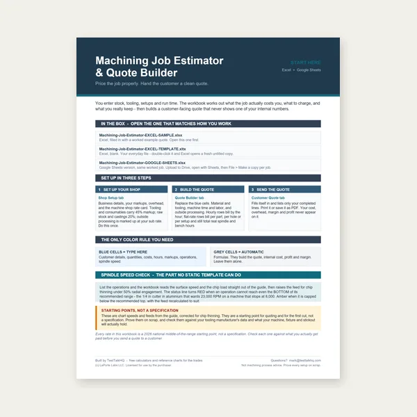
Quote shop work and check operations against your spindle's top speed.
Excel or Google Sheets. Best on a computer.
$29.00
Buy
Card, 27-page guide and the estimator workbook. All six files.
Excel or Google Sheets. Best on a computer.
$34.99
$45.98 if bought separately — save $10.99
BuyCheckout opens in a new tab.
Measurement, cutting fluid, and assembly lubricants for reliable parting operations

Accurate measurement before and after parting keeps your workpieces in spec. The Starrett EC799A reads to 0.0005 inch with carbide-tipped jaws and a clear LCD display. When you’re parting to a shoulder or a specific length, this is the caliper that confirms you’re where you need to be before the blade completes the cut.
Check Price
Parting operations generate concentrated heat in a very narrow cutting zone. Without cutting fluid, that heat builds fast, work-hardens the cut face in stainless, and glazes the blade. Tap Magic applied to the parting blade and workpiece keeps temperatures down, prevents blade loading, and dramatically improves cut quality in steel and stainless.
Check Price
Anti-seize on toolpost bolts and parting blade holders prevents galling and makes future tool changes faster. On any threaded fixture that gets tightened repeatedly under vibration, a thin coat of anti-seize is cheap insurance against seized fasteners down the road.
Check PriceAs an Amazon Associate, TestTalkHQ earns from qualifying purchases.
One of the most frustrating parting problems is a finished part dropping into the chip tray and getting dinged or damaged. A few approaches prevent this. For small parts, hold a cloth or your hand beneath the workpiece as the blade nears completion — the part drops softly. For threaded parts or precision ODs, wrapping a cloth around the part and gripping it lightly with your hand controls the drop without affecting the cut. For very small parts, a piece of foam or a rag in the chip tray absorbs the impact. On CNC lathes, a parts catcher handles this automatically. On a manual lathe, the cloth method is the standard shop solution.
Parting in a 3-jaw scroll chuck is the standard setup and works well for concentric, round stock. The 4-jaw independent chuck provides more rigidity for irregular or off-center work but requires careful setup to ensure the parting groove is centered on the spindle axis. An out-of-center parting cut creates an interrupted cut condition — the blade engages and disengages with each revolution — which dramatically increases chatter and blade loading. If you’re parting off-center work in a 4-jaw, reduce RPM significantly and use a very consistent feed. Concentric work in either chuck should be straightforward with correct speed and feed.
Mounting the parting tool in an inverted position on a rear toolpost is a technique used by many experienced manual lathe operators. The blade cuts in an inverted orientation, which means that cutting forces push the blade away from the work rather than into it — reducing chatter significantly. The spindle must run in reverse when using a rear toolpost. Not all lathes accommodate rear toolpost parting, and the setup requires a dedicated rear toolpost holder, but machinists who use it consistently report better surface finish and fewer blade breaks, especially in steel and stainless.
Parting on the lathe makes sense when you need a clean, square face on a turned workpiece and don’t want to re-chuck after sawing. It’s also faster than unclamping, sawing, and re-chucking for short production runs. Sawing makes more sense when the stock is too large in diameter for your parting blade to reach center, when the material is particularly prone to chatter (like large-diameter stainless), or when you have a large batch of raw stock to cut to length before turning. As a rule: if the part is already in the chuck and the diameter is under 3 inches, parting is usually faster. Larger or more difficult stock favors the saw.