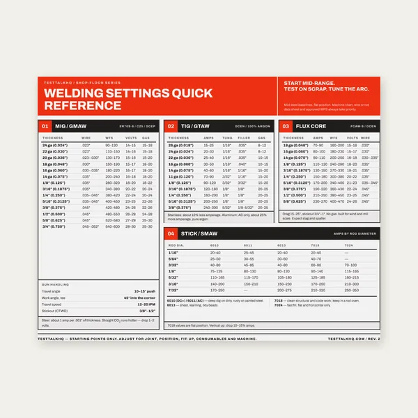
Welding Reference Card
One page. MIG, TIG, stick and flux core settings by thickness.
$3.99
BuyEvery common weld symbol, supplementary mark, and dimension callout explained
Weld symbols are the language of fabrication drawings. Every dimension, joint type, finish requirement, and special instruction gets communicated through a standardized symbol system defined by AWS A2.4. If you can't read weld symbols, you can't build to a drawing. This guide covers every common weld symbol, what each element means, and how to read a complete weld symbol from reference line to tail.

Every weld symbol is built from the same components. Understanding each part is the foundation for reading any weld symbol on any drawing.
| Element | Location | Meaning |
|---|---|---|
| Reference line | Horizontal baseline | Foundation of every weld symbol — everything attaches to this line |
| Arrow | Left end of reference line | Points to the joint being welded |
| Weld symbol | On or below/above reference line | Identifies the weld type (fillet, groove, plug, etc.) |
| Size | Left of weld symbol | Weld leg size (fillet) or groove depth |
| Length | Right of weld symbol | Length of the weld |
| Pitch | After length with dash | Spacing of intermittent welds (e.g. 2-6 = 2 in weld, 6 in spacing) |
| Angle | Inside groove symbol | Groove angle in degrees |
| Root opening | Inside groove symbol | Gap at root of groove weld |
| Finish symbol | Above/below weld symbol | C = concave, F = flush, G = grind |
| Tail | Right end of reference line | Specification, process, or note reference |
| Weld all around | Circle at arrow junction | Weld continuously around entire joint perimeter |
| Field weld | Flag at arrow junction | Weld to be made in the field, not the shop |
Arrow side means the side of the joint the arrow physically points to. Symbols placed below the reference line apply to the arrow side. Symbols placed above the reference line apply to the other side — the face opposite where the arrow lands.
When both sides need welding, you'll see symbols above and below the line — read each independently because leg sizes, lengths, and finishes can differ. The reference line itself never moves; only the placement of the weld symbol and dimensions changes which face of the joint is affected.
| Weld Type | Symbol Shape | Common Use | Key Dimensions |
|---|---|---|---|
| Square Groove | Two vertical lines | Thin material butt joints | Root opening |
| Single V-Groove | V shape opening upward | Plate butt joints | Groove angle, root opening, depth |
| Double V-Groove | V shapes opening both directions | Heavy plate, balanced distortion | Groove angle, depth each side |
| Single Bevel | One vertical, one angled line | T-joints, one-side access | Bevel angle, root opening |
| Double Bevel | Bevel both sides | Heavy T-joints | Bevel angle each side |
| Single U-Groove | U shape | Heavy plate, less filler than V | Groove angle, root radius |
| Single J-Groove | J shape | T-joints, less distortion than bevel | Groove angle, root radius |
| Flare V-Groove | Two curved lines flaring out | Round bar to round bar | Effective throat |
| Flare Bevel | One straight, one curved line | Round bar to flat plate | Effective throat |
Groove angle appears inside the V, bevel, U, or J symbol — typically shown in degrees (e.g. 60° for a standard V-groove). This is the included angle of the groove prep, not the bevel angle on one plate face.
Root opening is the gap left at the bottom of the groove before welding. It's shown inside the symbol or noted as (R) with a dimension. Root opening allows the root pass to achieve full penetration; too little risks lack of fusion, too much requires more filler and can increase distortion.
The fillet weld symbol is a right triangle. The vertical leg of the triangle always faces left regardless of which side of the joint the weld is on. The number to the left of the symbol is the leg size. The number to the right is the weld length. If no length is specified the weld runs the full length of the joint.
For intermittent fillet welds the length and pitch are shown as two numbers separated by a dash — for example 3-8 means 3-inch welds spaced 8 inches apart center to center. The total number of welds can be specified in parentheses.
A fillet weld symbol both above and below the reference line means weld both sides. The sizes may differ on each side — read them independently. Always verify the specified leg size against AWS D1.1 minimum fillet weld sizes for the base metal thickness before welding. Use our Fillet Weld Strength Calculator to check load capacity against throat size.
A plug weld is made through a hole in one piece of metal to fuse it to the piece beneath. The symbol is a rectangle on the reference line. The hole diameter is shown to the left, depth of fill to the right, and the angle of countersink inside the symbol if applicable. Plug welds are common in automotive and sheet metal work where lap joints need additional fastening points.
A slot weld is similar but the hole is elongated. The symbol is the same rectangle but the length and width of the slot are specified. Slot welds appear on structural drawings where a standard plug weld would not provide enough weld area for the required shear load.
Spot welds are resistance welds — the symbol is a circle on the reference line. The diameter of the nugget is shown to the left, number of spots in parentheses, and pitch to the right. Spot weld symbols appear on sheet metal and automotive drawings and are also used for arc spot welds (Dardelet welds) on light gauge steel decking.
Seam welds are continuous resistance welds — the symbol is a circle with two horizontal lines through it. Length and pitch follow the same convention as fillet welds. Both spot and seam weld symbols may appear with a process designation in the tail to distinguish resistance welding from arc welding processes.
| Symbol | Name | Meaning |
|---|---|---|
| Circle at reference line junction | Weld All Around | Weld completely around the joint perimeter with no gaps |
| Flag at reference line | Field Weld | Make this weld at the job site, not in the fabrication shop |
| Straight line contour | Flush Finish | Weld face to be finished flush with the base metal surface |
| Convex arc contour | Convex Finish | Weld face to be left convex (as welded or built up) |
| Concave arc contour | Concave Finish | Weld face to be finished concave |
| G below contour | Grind | Finish method: grind to achieve the specified contour |
| M below contour | Machine | Finish method: machine to achieve the specified contour |
| C below contour | Chip | Finish method: chip to achieve the specified contour |
| Rectangle on ref line | Backing | Backing bar or strip used on the root side |
| M in rectangle | Melt-Through | Complete fusion through the root — visible on other side required |
Multiple supplementary symbols can appear on a single welding symbol. Read them in combination: a circle (all around) plus a flag (field weld) means weld the entire perimeter on site. A flush contour with G below it means grind the weld face flush after welding. Always apply every symbol on the reference line — missing one supplementary mark is a common inspection failure.
Consider this welding symbol: a fillet weld with 3/8 to the left of the triangle, 4 to the right, the fillet symbol both above and below the reference line, a circle at the arrow junction, a flag on the reference line, and a flush contour with G below the weld symbol. Reading left to right: the arrow points to the joint. Below the line is a 3/8-inch leg fillet on the arrow side, 4 inches long. Above the line is the same — 3/8-inch leg, 4 inches on the other side. Both sides get fillet welds.
The circle means weld all around the joint perimeter — no gaps, continuous weld following the full outline. The flag means this weld is made in the field, not in the shop. The flush contour with G means grind each fillet face flush with the base metal after welding. The welder's job: travel to site, weld 3/8 fillets on both faces, 4 inches per segment, continuously around the joint, then grind flush. For interactive lookups by weld type, use our Weld Symbol Reference Tool. For joint geometry, see the Weld Joint Design Guide, Weld Joint Design Calculator, and Fillet Weld Strength Calculator. For when structural code compliance applies, read What Is AWS D1.1 and When Does It Apply?.
One page. MIG, TIG, stick and flux core settings by thickness.
$3.99
Buy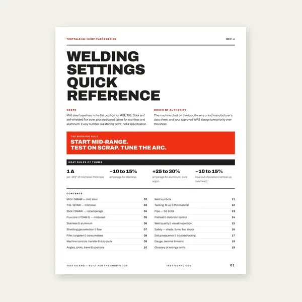
19 pages. Four processes, stainless and aluminum, symbols and inspection.
$12.99
Buy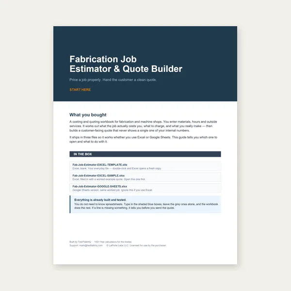
Price the job, then hand over a quote with no internal numbers.
Excel or Google Sheets. Best on a computer.
$29.00
Buy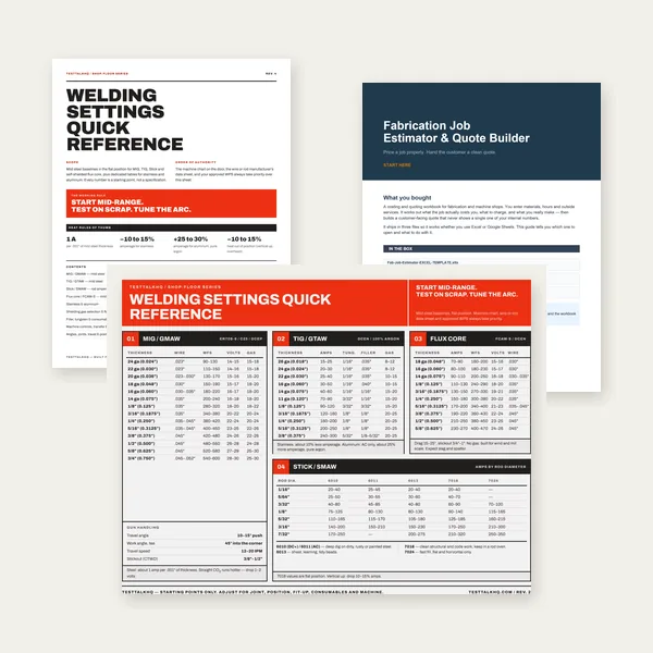
Card, 19-page guide and the estimator workbook. All six files.
Excel or Google Sheets. Best on a computer.
$34.99
$45.98 if bought separately — save $10.99
BuyCheckout opens in a new tab.
Grinders, chipping hammers, and holders for reading drawings and executing welds on the floor
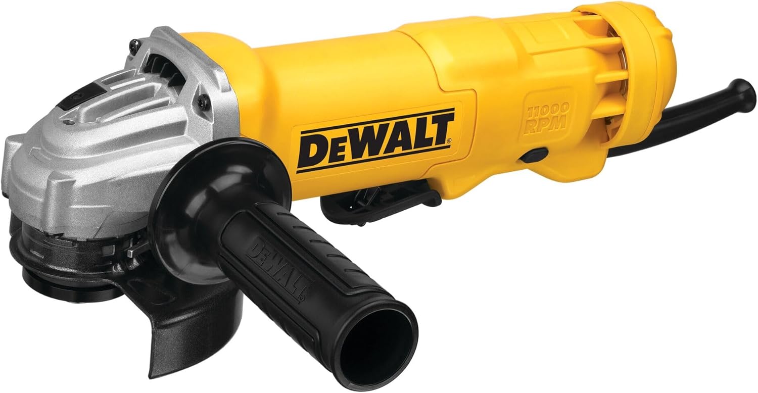
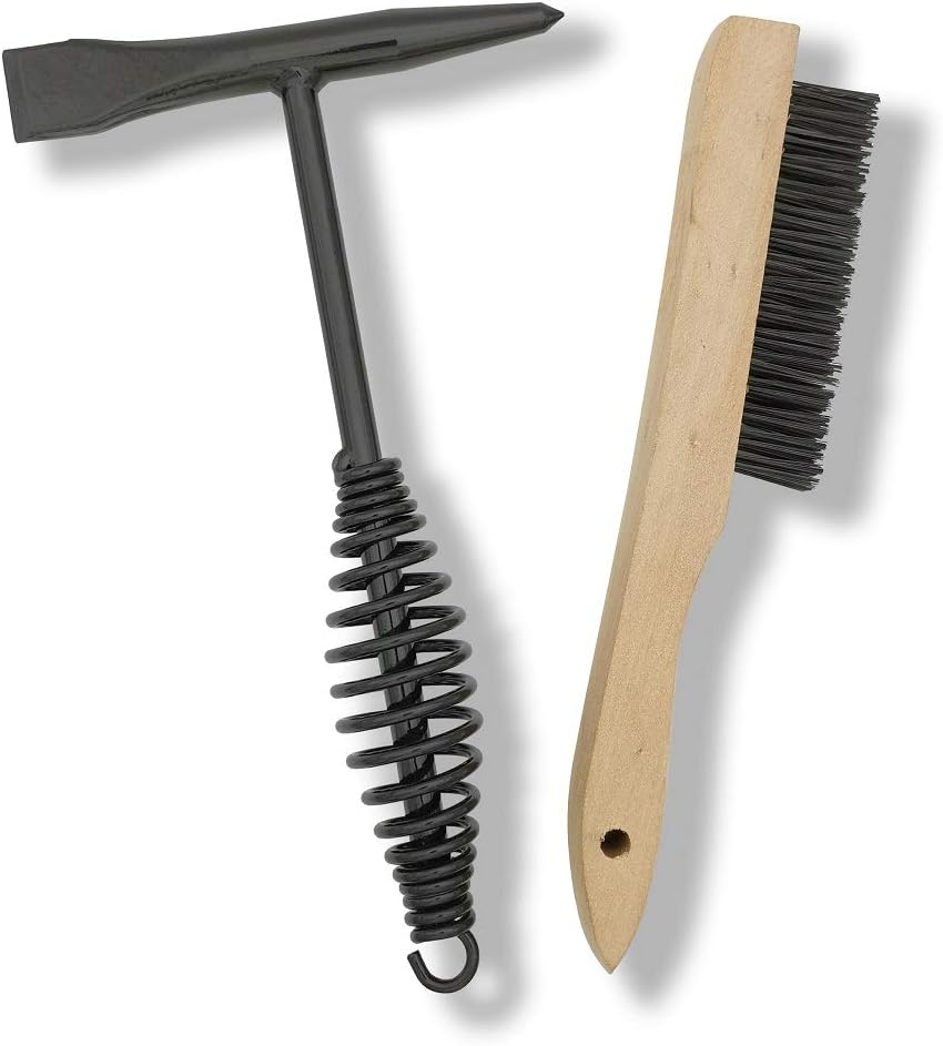
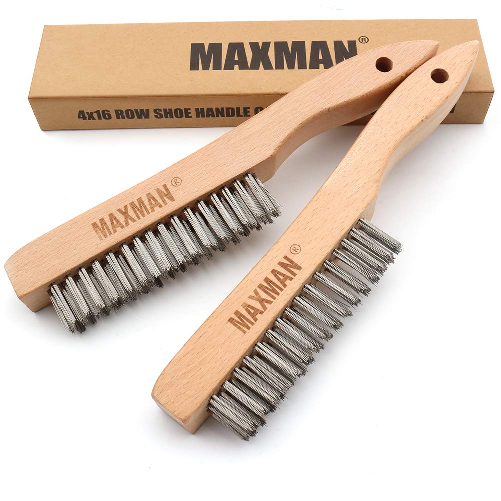
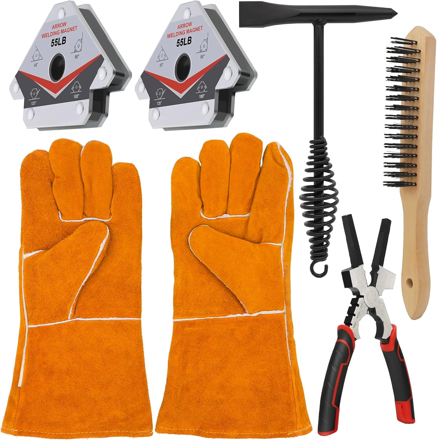
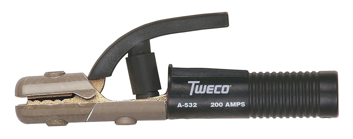
As an Amazon Associate, TestTalkHQ earns from qualifying purchases.
The four most common errors when reading weld symbols: ignoring the arrow side vs other side distinction, missing the pitch on intermittent welds, confusing groove depth with groove angle, and missing the weld all around circle.
Any one of these mistakes can result in a weld that doesn't meet the drawing requirement and fails inspection. When in doubt, read every number and every supplementary mark before striking an arc.
A weld symbol refers specifically to the geometric symbol that identifies the weld type — the triangle, V, rectangle, or circle. A welding symbol is the complete assembly: reference line, arrow, weld symbol, dimensions, and all supplementary information.
The terms are often used interchangeably in the field but AWS A2.4 makes the distinction. The welding symbol is the full communication package; the weld symbol is just one component of it.
All weld symbols used in US fabrication and structural work are defined by AWS A2.4: Standard Symbols for Welding, Brazing, and Nondestructive Examination. It's updated periodically — the current edition is AWS A2.4:2012.
ISO 2553 is the international equivalent used in Europe and Asia. The two standards use similar concepts but differ in symbol placement conventions — always confirm which standard a drawing follows before reading it.
Certified welding inspectors (CWIs) use the drawing's weld symbols to verify that welds are made to specification. They check size, length, location, finish, and process against what the symbol requires.
If a weld doesn't match the symbol — wrong size, missing weld, wrong finish — it's a nonconformance that requires repair or disposition. Understanding weld symbols is not just for welders — it's essential for anyone signing off on fabricated assemblies.