Weld Symbol Reference Tool
Interactive AWS weld symbol lookup — groove, fillet, plug, slot & more
Look up any common weld symbol used on structural and fabrication drawings. Click a weld type below for the full symbol breakdown, arrow-side rules, key dimensions, and supplementary symbols.
Pair with our Weld Joint Design Calculator and Fillet Weld Strength Calculator. Browse more free welding tools.
Select a weld type to expand the full AWS symbol breakdown. No page reload — click another card to switch.
Fillet Weld
Right triangle placed on the reference line with the vertical leg on the left and the hypotenuse sloping down to the right. No groove prep is shown.
Below the line = fillet on the arrow side of the joint. Above the line = fillet on the other side. Both sides = fillet welds on both faces.
T-joints, lap joints, corner joints, gussets, brackets, and most everyday structural connections.
Number to the left of the symbol = leg size (e.g. 1/4). Number to the right = weld length. Intermittent: length-pitch (e.g. 2-6 = 2 in welds every 6 in).
- Weld all around (circle)
- field weld (flag)
- flush/convex/concave finish contours on the triangle face.
Single V-Groove
V-shaped symbol on the reference line — two lines meeting at a point below the line, opening toward the arrow side.
Symbol below the line = V-groove on arrow side only. Above = groove on other side. Used for butt joints requiring full penetration from one side.
Plate butt joints, pipe groove prep, structural CJP welds with access from one side.
Angle inside parentheses (e.g. (60°)). Depth or groove detail in parentheses. Root opening (R) when specified. Weld size/contour on symbol.
- Backing bar symbol
- melt-through (M)
- weld all around
- field weld.
Double V-Groove
V on both sides of the reference line — two V symbols, one above and one below, for grooves on both faces.
Symbols on both sides of the line indicate double-sided groove prep on a butt joint. Balanced welding reduces distortion.
Heavy plate butt joints, pressure vessel shells, structural members where distortion control matters.
Groove angle in parentheses on each symbol. Root face and root opening per WPS. Often sequenced alternating sides.
- Weld all around
- field weld
- backing when required on first pass.
Single Bevel Groove
Single angled line sloping from the reference line — a half-V on one side only.
Below the line = bevel on arrow side. Above = bevel on other side. Common on T-joints with one-sided access.
T-joints requiring CJP, heavy columns to base plates, one-side access joints.
Bevel angle in parentheses (typically 45°). Groove depth, root opening (R), and effective throat when specified.
- Backing weld symbol
- field weld
- weld all around on closed sections.
Double Bevel Groove
Bevel symbols on both sides of the reference line — angled lines above and below.
Indicates bevels on both members or both sides of the joint for balanced groove prep.
Heavy T-joints, thick member connections, reduced distortion vs single-sided bevel.
Angle per side in parentheses. Root opening and depth per AWS detail. Sequence notes in tail when needed.
- Backing
- melt-through
- field and all-around symbols as applicable.
Single U-Groove
U-shaped curved symbol attached to the reference line — curved bottom with straight sides.
Below line = U-groove on arrow side. Less filler than V-groove for same thickness.
Heavy plate butt joints, pressure vessels, jobs where weld volume cost is significant.
Groove angle and root radius in parentheses or tail note. Root face dimension. Depth of groove.
- Backing bar
- field weld
- all around on circular joints.
Single J-Groove
J-shaped symbol — straight face with curved root portion, like a U on one side only.
Below = J-groove on arrow side. Common on T-joints where a full bevel would remove too much metal.
T-joints on thick plate, reduced distortion vs single bevel, limited access roots.
Root radius, groove angle, and depth in parentheses or specification tail.
- Backing weld
- field weld
- contour finish symbols.
Square Groove
Two parallel vertical lines on the reference line (or a rectangle on the line) indicating a square butt with no bevel.
Below or on line = square groove on arrow side. Used when material is thin enough for no bevel.
Thin sheet and plate butt joints (often t ≤ 3/16 in), square-cut edges with root opening.
Root opening dimension when gap is required. No groove angle. Weld size for partial penetration when noted.
- Spacer or backing when shown; field weld and all around as needed.
Plug Weld
Circle on the reference line (filled or outlined) indicating a plug weld in a circular hole.
Symbol placement follows arrow/other-side rules. Arrow points to the member containing the plug holes.
Joining overlapping plates, filling drilled holes, sheet metal attachments, architectural steel.
Diameter of plug in fraction or decimal to the left. Depth or pitch when multiple plugs. Spacing in tail or note.
- Number of plugs
- pitch spacing
- countersink detail in tail specification.
Slot Weld
Rectangle on the reference line indicating weld in an elongated slot.
Arrow side vs other side per standard reference line rules. Points to slotted member.
Overlapping plates, structural connections using slots instead of round plugs, architectural fab.
Slot width and length dimensions. Pitch between slots. Depth of fill when partial.
- Field weld
- number and spacing in tail
- contour if flush required.
Spot Weld
Circle on the reference line (resistance/spot context) or circle at arrow side — process-specific; on drawings often with resistance weld note in tail.
Arrow points to the joint location. Symbol on line indicates spot location relative to arrow side convention.
Sheet metal, automotive, light gauge fabrication, resistance welding applications.
Spot diameter, number of spots, pitch spacing. Strength per spot per specification.
- Process note in tail (RSW)
- pitch pattern
- sheet thickness in WPS.
Seam Weld
Circle with parallel lines or a circle flagged as continuous seam — indicates length of continuous or intermittent seam.
Follows reference line side rules for which member receives the seam weld.
Fluid-tight joints, tanks, sheet lap seams, resistance seam welding.
Seam width, length, pitch for intermittent seam. Start/stop locations on drawing.
- Weld all around when continuous perimeter; process in tail.
Back / Backing Weld
Rectangle below the reference line (backing bar) or a weld symbol on the opposite side indicating back gouge/back weld sequence.
Backing symbol below line = backing bar or backing weld on arrow side. Used with groove welds for root support.
CJP groove welds requiring root backing, back gouge and weld sequences on pressure pipe.
Backing material spec in tail. Back weld size when shown as fillet on reverse side.
- Often paired with groove symbol; melt-through (M) when root reinforcement required.
Surfacing Weld
Surface contour symbol — multiple parallel lines or a band symbol indicating build-up on a surface rather than a joint.
Arrow points to the surface to be built up. Not a joint between two members — deposit on base metal face.
Hardfacing, wear surfaces, build-up repair, corrosion-resistant overlay.
Width and thickness of build-up, number of layers, hardness spec in tail.
- Process and electrode classification in tail; preheat/postheat notes.
Flange Weld
Flange edge weld symbol — curved or angled symbol at edge joint indicating weld on a flanged edge preparation.
Arrow points to flanged edge. Symbol on line indicates weld on that edge preparation.
Edge joints, flanged light-gauge connections, certain sheet metal edge welds.
Flange radius, weld size, length along edge.
- All around on closed flanged sections; contour finish symbols.
Supplementary Symbol Reference
These modifiers appear on or near the reference line and change weld extent, location, or finish requirements.
| Symbol | Meaning |
|---|---|
| Circle on reference line | Weld all around |
| Flag on reference line | Field weld |
| Straight line on weld symbol | Flush finish |
| Convex arc | Convex finish |
| Concave arc | Concave finish |
| Rectangle below reference line | Backing |
| M in rectangle | Melt-through |
| (R) | Root opening specified |
⚡ Recommended Shop Tools for Weld Layout
Grinders, chipping hammers, and holders for reading drawings and executing welds on the floor
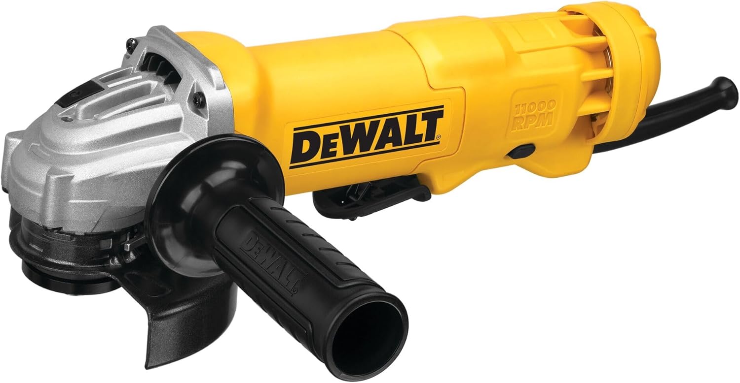
DEWALT Angle Grinder 4.5 Inch 11 Amp
- Bevel and groove plate edges
- 11 amp motor for heavy prep
- Match drawing groove angles
- Deburr root faces quickly
- Shop standard for weld prep
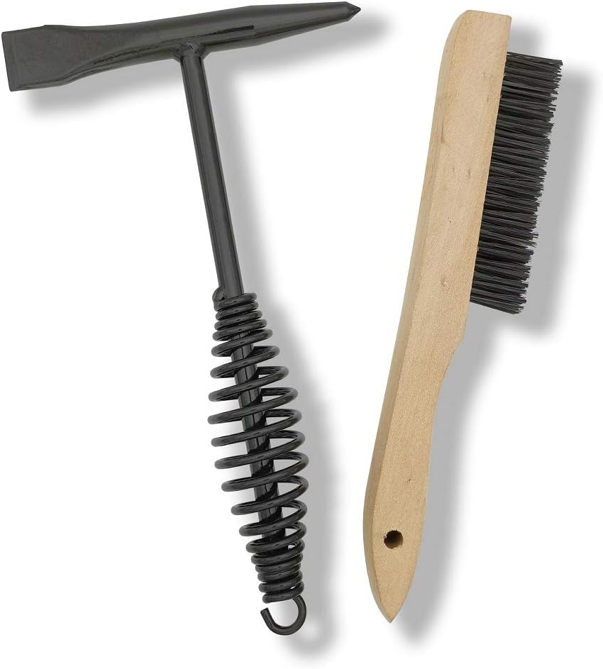
VASTOOLS Welding Chipping Hammer
- Slag removal after root passes
- Spring handle reduces shock
- Inspect groove before fill
- Essential for SMAW/FCAW
- Pairs with wire brush end
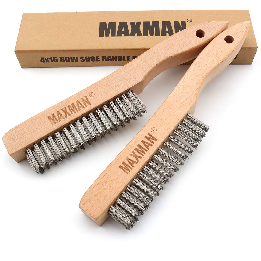
MAXMAN Wire Brush Heavy Duty Stainless 2-Pack
- Clean groove faces before welding
- Stainless bristles for tough scale
- 10-inch handle for leverage
- 2-pack shop value
- Prep per symbol spec
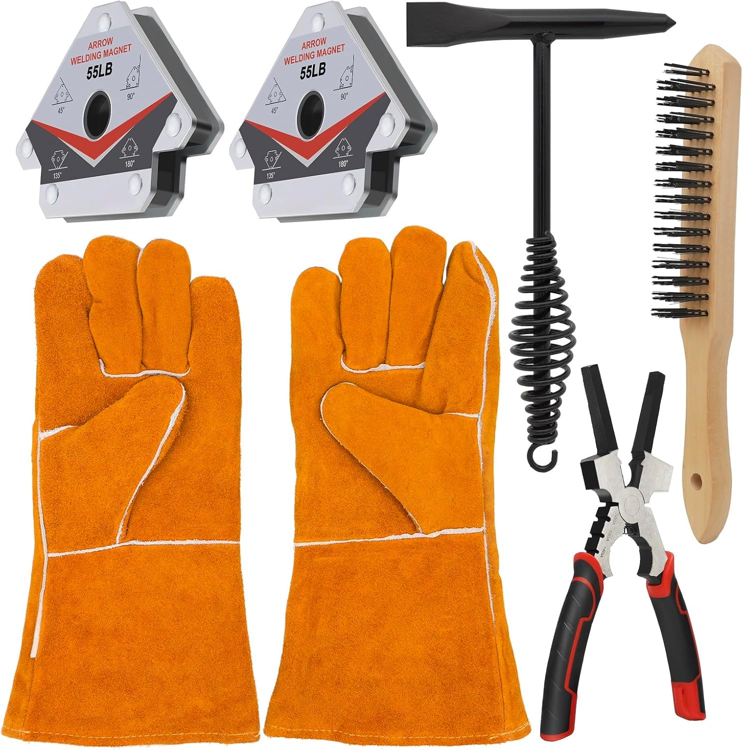
VASTOOLS Welding Accessories 6pc Set
- Chipping hammer & wire brush
- Magnetic squares for layout
- Complete starter kit value
- Field-ready carry pouch
- Mark-up and fit-up tools
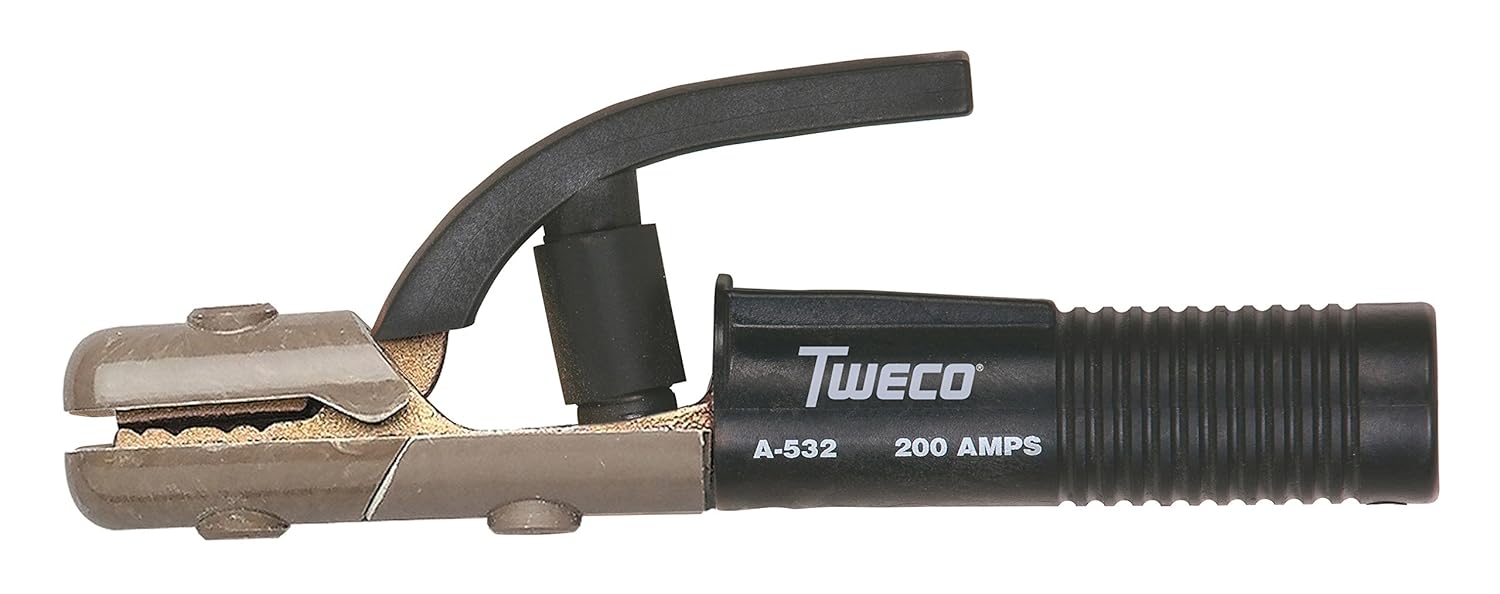
Tweco A532 Electrode Holder
- Secure rod grip for stick work
- Durable copper alloy jaws
- Comfort grip for long welds
- Industry-standard holder
- Execute symbol-specified joints
As an Amazon Associate, TestTalkHQ earns from qualifying purchases.
How to Read the Reference Line
Every weld symbol is built around a horizontal reference line with an arrow pointing to the joint. Symbols placed below the reference line apply to the arrow side of the joint. Symbols placed above the reference line apply to the other side.
A dashed line below or above indicates the other side — some older drawings use this convention. The tail at the right end of the reference line (when present) contains a specification, process, or note.
Arrow Side vs Other Side
Arrow side means the side of the joint the arrow is physically pointing to. Other side means the opposite face of the joint. For a T-joint for example, if the arrow points to the front face, a symbol below the line means weld the front face. A symbol above the line means weld the back face.
Both symbols present means weld both sides. This is one of the most common points of confusion for new welders reading drawings.
Weld Size and Length on the Symbol
For fillet welds, the number to the left of the weld symbol is the leg size. The number to the right is the weld length. A dash and number after the length (e.g. 2-6) means 2-inch welds spaced 6 inches apart (intermittent fillet).
For groove welds, the number in parentheses is the groove depth, and the number outside is the groove angle. Always read both numbers — missing one means missing a critical dimension.
Field Weld and Weld All Around
The flag symbol on the reference line means the weld is to be made in the field (on-site) rather than in the shop. The circle at the junction of the arrow and reference line means weld all around the perimeter of the joint — no interruptions.
These two supplementary symbols are critical on structural and pipe drawings and are often missed by welders unfamiliar with symbol notation.