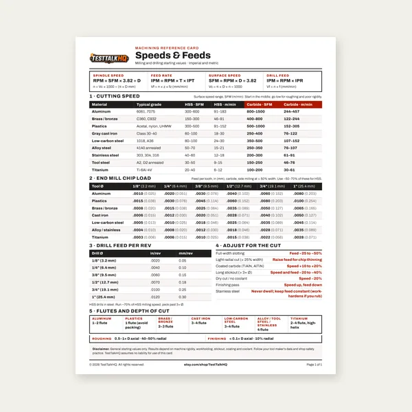
Machining Speeds & Feeds Card
One page. Speeds, chip load and drill feed, imperial and metric.
$3.99
BuyAngles, depths, pilot holes, and tool selection — everything you need to get the geometry right the first time.

A countersink is a conical recess machined at the entrance of a hole. Its purpose is to receive the angled underside of a flat-head or oval-head fastener so the head sits flush with — or below — the workpiece surface. The cone angle must match the underside geometry of the screw head precisely. Get the angle wrong by even a few degrees and the fastener contacts only the outer rim of the countersink, concentrating load at the edge instead of distributing it across the full bearing surface. The result is a fastener that feels tight but isn't, and a countersink that brinells and widens under load.
A counterbore is a cylindrical flat-bottomed recess, typically larger in diameter than the clearance hole below it. Its purpose is to receive a socket head cap screw, hex bolt, or button head fastener and allow that head to sit flush or below the surface where a flat-head fastener is not appropriate or available. Unlike a countersink, the geometry is defined by two dimensions — diameter and depth — rather than an angle. Both must be sized to match the specific fastener.
The choice between the two is driven by the fastener, not preference. Flat head screws require a countersink. Socket head cap screws, button heads, and hex bolts require a counterbore. Some assemblies use both: a counterbore to clear the hex nut on the back side of a plate while a countersink seats the fastener head on the front.
Countersink angles are included angles — the total angle of the cone measured from one side to the other through the tip. Each standard angle serves a specific class of fastener.
82° is the standard for inch-series flat head machine screws per ASME B18.6.3. If you are using #0 through 1" flat head screws with UNC or UNF threads bought from any US industrial supplier, the countersink angle is 82°. This is the most common angle in general machining and fabrication work in North America. Using a 90° countersink on an 82° fastener causes the head to rock on its outer rim — a subtle misfit that most people miss until the fastener backs out under vibration.
90° covers metric flat head screws per ISO 7721 and DIN 965, most sheet metal screws, and the majority of wood screws. If you are working with metric fasteners from European suppliers or using thread-forming screws in sheet metal, 90° is the correct angle. It is also the standard angle for general chamfering and deburring operations where precise fit is not required.
100° is the aerospace standard. AN426 countersunk bolts, AN507 screws, MS24694 flat head screws, and most NAS countersunk fasteners all use a 100° included angle. This wider angle distributes load across a larger bearing surface at the joint, which is why aerospace and high-fatigue applications use it. A 100° countersink in a structural fabrication using AN hardware is not optional — the wrong angle changes the load distribution and the fastener's ability to develop its required clamp load.
118° matches the standard point angle of HSS twist drills. A 118° countersink is used primarily to chamfer the entrance of a drilled hole — removing the burr left by the drill and creating a clean lead-in for assembly. It is not paired with a specific fastener. You will also find 118° countersinks used to create a matching chamfer on the underside of a hole so a bolt head or washer seats cleanly without rocking on a burr ridge.
Countersink depth is determined by the required surface diameter — which must match the maximum head diameter of the fastener — and the countersink angle. The geometry is a right triangle: the half-angle from the cone's center axis equals half the included angle, the radius at the surface equals the head diameter divided by two, and the depth is the adjacent side of that triangle.
The formula is:
Depth = (Head Diameter / 2) / tan(Included Angle / 2)
For an 82° countersink with a #10 flat head machine screw (head diameter 0.400"):
Depth = (0.400 / 2) / tan(41°) = 0.200 / 0.8693 = 0.230"
For a 90° countersink with the same diameter:
Depth = 0.200 / tan(45°) = 0.200 / 1.000 = 0.200"
For a 100° countersink at the same diameter:
Depth = 0.200 / tan(50°) = 0.200 / 1.192 = 0.168"
The shallower the included angle, the deeper the countersink must go to achieve the same opening diameter. An 82° countersink requires significantly more depth than a 100° countersink for the same fastener head size. This matters when you are working near the back side of a plate — a thin workpiece may not have room for a full 82° countersink without breaking through.
Add 0.005"–0.010" to the calculated depth to ensure the fastener head sits fully flush and the top of the head has slight clearance below the surface plane. A fastener that is 0.003" proud looks flush until you run a straight edge across it and then it telegraphs through paint or a mating surface. Use the Countersink & Counterbore Depth Calculator at TestTalkHQ to run the geometry for any angle and head diameter combination without working through the trigonometry manually.
A counterbore must clear the fastener head diameter and provide enough depth so the head sits at or below the surface. For socket head cap screws (the most common counterbore application), ASME B18.3 provides the standard counterbore dimensions:
| Screw Size | Head Diameter (in) | Head Height (in) | Counterbore Dia (in) | Counterbore Depth (in) |
|---|---|---|---|---|
| #6-32 | 0.226 | 0.138 | 0.238 | 0.145 |
| #8-32 | 0.270 | 0.164 | 0.284 | 0.172 |
| #10-32 | 0.312 | 0.190 | 0.328 | 0.199 |
| 1/4-20 | 0.375 | 0.250 | 0.390 | 0.260 |
| 5/16-18 | 0.469 | 0.312 | 0.484 | 0.323 |
| 3/8-16 | 0.562 | 0.375 | 0.581 | 0.390 |
| 1/2-13 | 0.750 | 0.500 | 0.775 | 0.510 |
The counterbore diameter is typically 0.010"–0.020" larger than the head diameter — enough clearance to drop the fastener in cleanly without the head binding on the bore wall, but tight enough that the fastener is visually centered when assembled. The counterbore depth equals the head height plus 0.005"–0.010" so the head is fully recessed with a small amount of clearance below the surface plane.
For non-standard fasteners or button head screws where published counterbore tables may not apply, measure the actual head diameter with a caliper and add 0.015" for the bore diameter. Measure the actual head height and add 0.005"–0.010" for the bore depth. These are safe working allowances that apply across materials and fastener types.
The pilot hole — the clearance hole for the fastener body — must be drilled before either the countersink or counterbore operation, not after. Countersinking over an existing hole is more stable than attempting to start a countersink on a flat surface; the pilot hole centers the tool. Counterboring over a pilot hole aligns the bore concentrically with the fastener path.
For clearance holes in non-threaded through-hole applications, use a drill diameter that provides a free fit over the fastener body: typically body diameter plus 0.010"–0.015" for general fabrication, or body diameter plus 0.002"–0.005" for a close fit where alignment between mating parts matters. A 1/4-20 SHCS has a body diameter of 0.250"; a free-fit clearance hole is 0.266" (letter F drill at 0.257" for close fit, or 17/64" at 0.266" for free fit).
For threaded holes where the countersink or counterbore precedes tapping, drill to the tap drill diameter first. Then machine the countersink or counterbore. Then tap. This order prevents the tap from being disrupted by a countersink that was cut into an undrilled or partially drilled surface.
A single-flute (also called single-edge or piloted) countersink cuts aggressively on one edge. The lack of symmetry means the tool tends to chatter — oscillate at its natural frequency — in ductile materials like aluminum unless you use very low RPM or a pilot that prevents the tool from wandering. For hand drilling in soft materials, single-flute countersinks with an integral pilot are practical. On a drill press or mill, multi-flute tools almost always produce a better result.
Three, four, and six-flute countersinks cut on multiple edges simultaneously, which reduces chatter dramatically and produces a smoother, rounder countersink. In steel and stainless, a multi-flute HSS or carbide countersink is the correct tool. Six-flute tools produce the finest finish and are used in production environments where surface quality matters. Three-flute tools are the most common and the best general-purpose choice for shop use.
HSS countersinks handle aluminum, mild steel, brass, and plastics without issue and are the standard shop tool for general work. For stainless steel, titanium, hardened steel, and abrasive materials, carbide-tipped or solid carbide countersinks are necessary — HSS work-hardens stainless at the cutting edge and dulls quickly in hard materials. Carbide requires lower RPM than HSS at a given diameter; do not run carbide at HSS speeds in hard materials or you will chip the cutting edges.
Surface footage for countersinking in common materials using multi-flute HSS: aluminum 200–350 SFM, mild steel 60–90 SFM, stainless steel 20–40 SFM (use carbide). Calculate RPM from SFM and the countersink's maximum cutting diameter: RPM = (SFM × 3.82) / diameter. Use the larger diameter of the countersink, not the pilot hole diameter — the outer edge is where the speed matters.
A drill press gives you depth control through the quill stop, which makes it the preferred tool for production countersinking where every hole must be identical. Set the quill stop so the countersink reaches the calculated depth plus 0.005". Lock the stop. Countersink the first hole, check the fastener fit (the head should sit flush to 0.005" below), and adjust the stop before running the remaining holes. Drill press tables allow the workpiece to be clamped flat, which prevents the conical tool from tilting and producing an off-angle countersink. Avoid hand-feeding by feel on a drill press — depth variation of 0.010" across a run of holes is visible and unacceptable in any precision assembly.
A mill gives you the most precise control over both depth and position. Program the countersink depth through the knee or quill DRO. Use the spindle speed closest to the calculated SFM for the material. On a manual mill, use the quill lock and fine-feed handwheel to reach the set depth. On a CNC, countersinking is a single canned cycle with diameter and angle inputs — confirm the tool library entry matches the actual countersink angle on the tool in the spindle; a tool library error here is one of the most common causes of wrong-angle countersinks in CNC shops.
Hand drilling countersinks is the least controlled option but is practical for installation work, field repairs, and non-critical applications. Use a countersink bit with a spring-loaded depth stop collar — these are widely available and index on the surface of the workpiece, stopping the countersink at a fixed depth relative to the surface. Without a depth stop, hand-drilled countersinks vary by 0.020"–0.050" in depth across a run, which is visible once fasteners are installed. Run at low speed, let the tool cut without forcing it, and check the first hole with the actual fastener before completing the run.
Using a 90° countersink for an 82° flat head screw (or vice versa) is the most damaging common error. The head contacts only the outer rim of the countersink rather than bearing across the full cone surface. The fastener rocks slightly, the contact zone brinells, the rim of the countersink enlarges over time, and the fastener eventually backs out or strips. Always identify the screw standard before selecting a countersink angle. When in doubt, measure the underside angle of the fastener head with a protractor or check the fastener specification sheet.
A countersink that is 0.010" too shallow leaves the fastener head proud of the surface. In structural applications this disrupts mating surface contact. In assemblies with covers or panels, it causes interference fits that deform the panel when fastened. The fix is to countersink to calculated depth plus 0.005"–0.010" and verify with the actual fastener before running all holes. Do not estimate depth by eye — the difference between flush and 0.010" proud is not reliably visible on a bare metal surface.
Attempting to countersink a flat surface without a pilot hole allows the tool to walk before it establishes its cut. The result is an off-center, slightly oval countersink that does not seat the fastener concentrically. Always drill the pilot hole first. Even a small center drill dimple gives a multi-flute countersink enough of a starting point to prevent walking.
Stainless steel work-hardens under the cutting edge when the tool rubs rather than cuts — which happens when speed is too high and feed rate is too low. Once work-hardened, the surface is significantly harder than the base material and dulls HSS cutting edges rapidly. In stainless: use carbide, run at 20–40 SFM based on the maximum countersink diameter, use cutting fluid generously, and keep the tool feeding. A dwell at depth with no feed generates heat and work-hardens the contact zone. Feed through to depth and retract — do not pause.
Use the calculated depth from the formula — (head diameter / 2) / tan(half-angle) — and add 0.005" for clearance. Set your depth stop to that value, countersink one hole, and check with a straight edge laid across the surface. The flat head should sit flush to slightly below the straight edge. If you have a dial indicator on the drill press quill, you can verify the actual depth reached against the calculated value without test-fitting every hole. The Countersink & Counterbore Depth Calculator gives you the target depth for any angle and head diameter combination in seconds.
No. The included angle of the countersink must match the included angle of the fastener's underside geometry. An 82° countersink cannot produce a 90° recess regardless of how you run it — the angle is fixed by the tool's geometry. If you regularly work with both inch-series (82°) and metric (90°) fasteners, you need both tools. Countersink sets that include 82°, 90°, 100°, and 120° are available from most tooling suppliers and are the practical solution for shops that see a mix of fastener standards. Keep them labeled — a countersink cutter without an angle marking is a problem waiting to happen.
A spotface is a shallow cylindrical recess — essentially a very shallow counterbore — machined to create a flat, clean bearing surface for a fastener head or washer on a rough or curved workpiece. Castings, weldments, and forged parts often have uneven surfaces where a bolt head would not seat flat without a spotface. The diameter matches the fastener head or washer OD; the depth is just enough to clean up the surface, typically 0.005"–0.030". A counterbore is cut to a specific depth that fully recesses the fastener head below the surface. Both use the same tools — a counterbore cutter at shallow depth is a spotface operation.
Chatter in aluminum is almost always caused by the combination of a single-flute countersink and too high a spindle speed. Single-flute tools cut on one side only, creating an imbalanced cutting force that excites the tool's resonant frequency. Aluminum's low cutting resistance means the tool deflects easily before re-engaging, setting up the chatter cycle. Fix: switch to a three or six-flute countersink, which distributes cutting forces evenly, and run at 150–200 SFM (lower than you would expect for aluminum) to prevent the tool from skipping across the surface. Make sure the workpiece is rigidly clamped — any movement of the part amplifies chatter. Cutting fluid helps in aluminum, but the tool geometry and speed change are the primary solutions.
One page. Speeds, chip load and drill feed, imperial and metric.
$3.99
Buy
27 pages. Milling, drilling, tapping, turning and CNC routing.
$12.99
Buy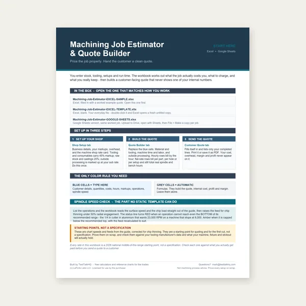
Quote shop work and check operations against your spindle's top speed.
Excel or Google Sheets. Best on a computer.
$29.00
Buy
Card, 27-page guide and the estimator workbook. All six files.
Excel or Google Sheets. Best on a computer.
$34.99
$45.98 if bought separately — save $10.99
BuyCheckout opens in a new tab.
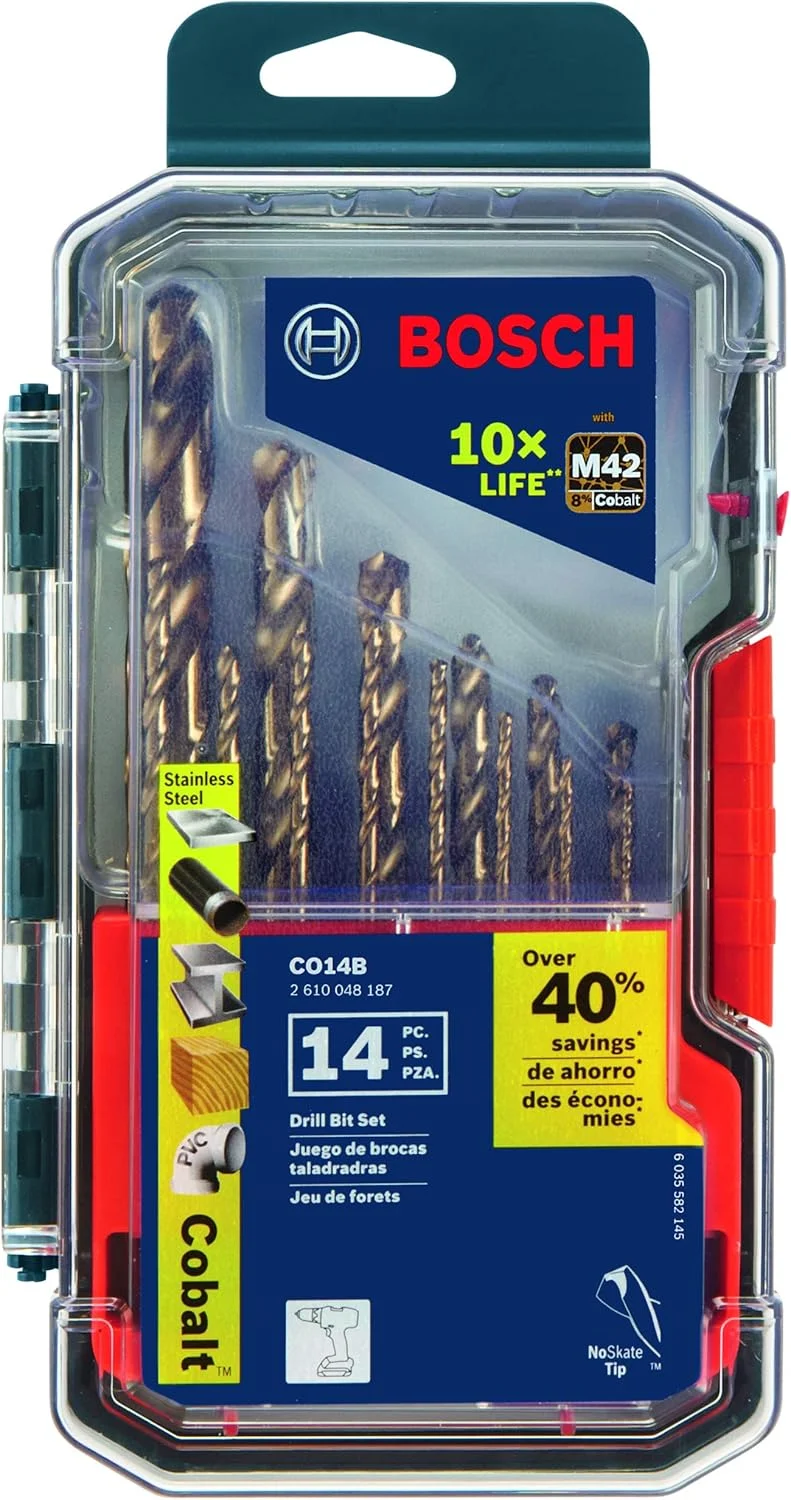
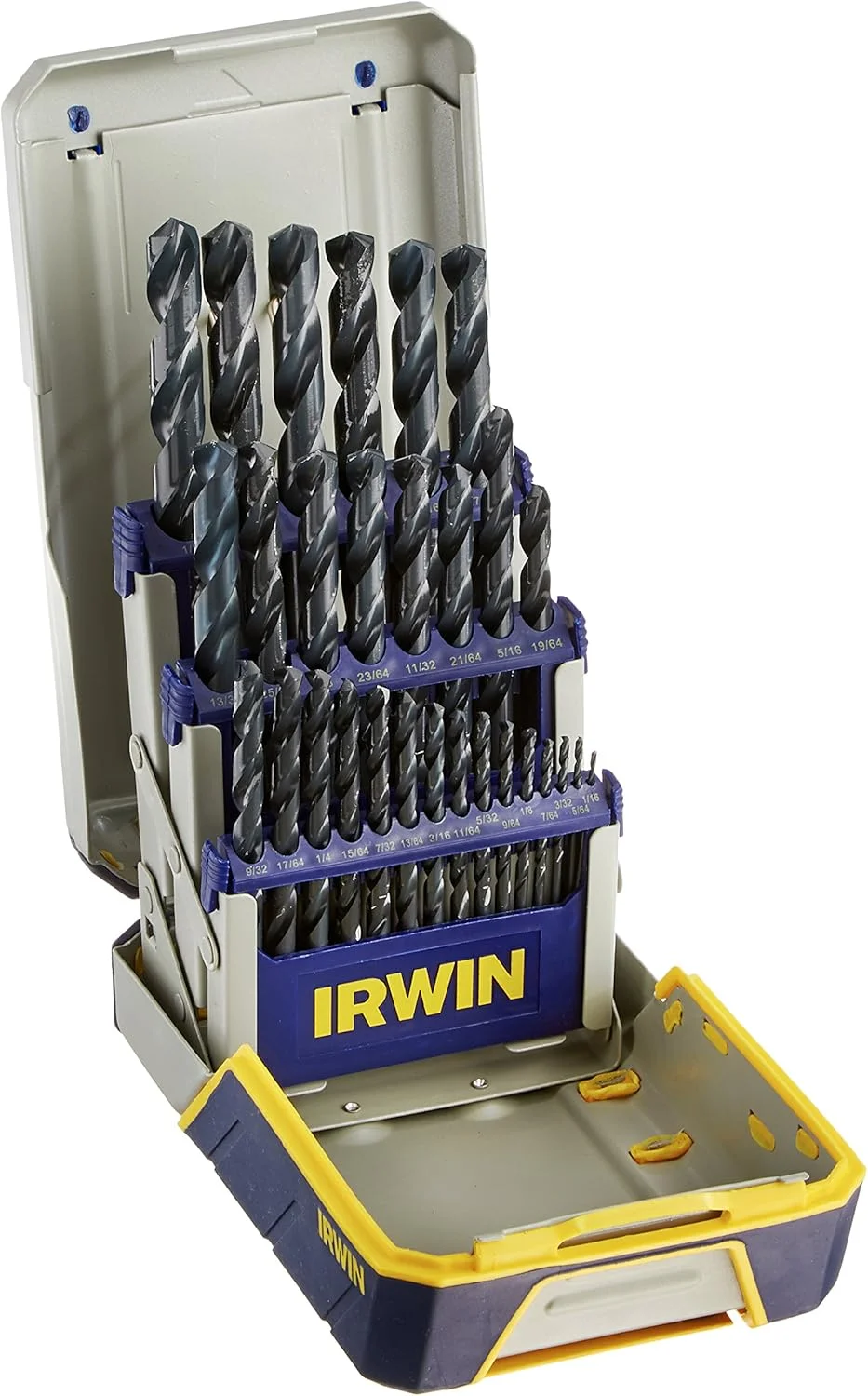
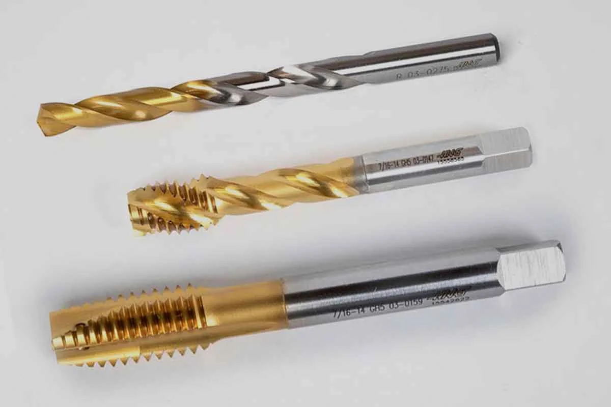
Pilot hole drill sets for accurate countersink and counterbore setup in any material
As an Amazon Associate, TestTalkHQ earns from qualifying purchases.
A drill press gives you controlled depth and perpendicularity that hand drilling can't match — essential when the countersink needs to be square to the surface and consistent across multiple holes. Set the depth stop on the drill press before cutting the first hole and test on scrap first. A mill gives you even more control and is the right tool for precision work where the countersink location and depth are held to tight tolerance. Hand drilling is acceptable for occasional light-duty work in soft materials, but even small angular errors produce visible gaps between the screw head and the material surface. Use a drill press or mill whenever the application matters.
A flat-head screw that sits above the surface instead of flush means one of three things: the countersink is too shallow, the countersink angle doesn't match the screw head angle, or the pilot hole was drilled off-center and the countersink tool followed it. Depth is the most common cause — running the countersink tool until it looks right by eye usually produces a hole that's 0.005 to 0.015 inches too shallow. Use the Countersink & Counterbore Depth Calculator to get the exact depth before you cut, and measure with a depth micrometer after. Angle mismatch produces a ring contact instead of full-face contact — the screw rocks in the hole and never seats flat regardless of how far you drive it.
Countersink tools run at lower RPM than twist drills of equivalent size. Running a countersink tool too fast in steel or stainless generates heat that dulls the cutting edges quickly, produces a rough finish in the countersink bore, and can cause chatter that leaves spiral marks on the chamfer face. In aluminum, high speed causes the tool to load up with built-up edge. A good starting point for HSS countersink tools is 300-600 RPM in mild steel and 150-300 RPM in stainless. Carbide countersink tools can run faster but still benefit from reduced speed and cutting fluid in hard materials. Let the tool cut — don't force it with high RPM and pressure.
Socket head cap screws are the most commonly counterbored fastener in machine shop work. The counterbore diameter needs to clear the head with just enough room to install and remove the screw — typically head diameter plus 0.010 to 0.015 inches for a close fit. Too tight and the screw won't drop in cleanly. Too loose and the head has visible slop that looks unprofessional and can cause issues in precision assemblies. Counterbore depth should equal head height plus your desired clearance below the surface — typically 0.005 to 0.020 inches below flush. The flat bottom of the counterbore must be perpendicular to the hole axis or the screw head will rock and apply uneven clamping force.