Sizing air for a machine full of cylinders is not one calculation, it is four decisions stacked on top of each other: what each cylinder consumes, how many of them move at once, what fraction of the shift the machine actually runs, and how much of the peak you intend to buy in compressor capacity versus store in a receiver. Get the order wrong and you either buy a compressor twice the size you need or spend a year wondering why a correctly sized one cannot keep up.
Start with a cylinder schedule, not a compressor catalogue
Before anything gets sized, write down every actuator on the machine in a single table. It takes twenty minutes and it is the difference between a defensible number and a guess. For each cylinder you want bore, rod diameter, stroke, working pressure, whether it is double-acting, and how many cycles it makes per minute when the machine is at full rate.
| Station | Bore × stroke (rod) | Type | Cycles / min | SCFM at 80 psig |
|---|---|---|---|---|
| Infeed stop | 0.75″ × 1″ (0.25″) | Spring return | 30 | 0.23 |
| Clamp (×2) | 1.5″ × 2″ (0.5″) | Double-acting | 30 | 2.22 |
| Press | 4″ × 6″ (1″) | Double-acting | 30 | 16.70 |
| Ejector | 1.125″ × 4″ (0.4375″) | Double-acting | 30 | 1.19 |
| Total | 20.34 | |||
Those SCFM figures are what the calculator produces for each row, with 6 feet of 0.17 inch tubing on each port. The total is just over 20 SCFM. Notice how lopsided it is: the press alone is more than 80 percent of the machine’s air demand, while the infeed stop — a cylinder that fires exactly as often — is about one percent of it. This is the normal shape of a cylinder schedule, and it tells you immediately where attention is worth spending.
Why the schedule beats a rule of thumb
The common shortcut is to size on horsepower per station or to take the machine builder’s nameplate SCFM and add a bit. Both fail in the same direction. Nameplate figures are frequently quoted at the machine’s design rate with no tubing losses and no allowance for the station you added last year. A schedule you built yourself can be re-run when the rate changes, which it will.
Decide what runs at the same time
The cylinder schedule gives you an average. What the compressor actually sees depends on whether those averages overlap.
For a single machine running a fixed sequence, the honest answer is usually that they do overlap, because the machine repeats the same cycle continuously and you are averaging over many cycles anyway. Adding the SCFM column straight down is correct.
Where simultaneity matters is across machines, and across cylinders and hand tools sharing one compressor. A blow-off gun used a few seconds a minute, a die grinder run intermittently, and an automated cell that never stops are three different demand shapes. Add continuous demands at full value. For intermittent ones, multiply by the fraction of the hour they are genuinely in use — and be honest about it, because this is where optimism gets punished.
Duty cycle is a separate question again
A machine that runs 40 minutes in every hour has a duty cycle of 67 percent, and its average demand over the hour is two thirds of its running demand. That average is what determines your electricity bill and whether a compressor can thermally survive the job. It is not what determines whether the machine works. The machine needs its full running demand delivered during those 40 minutes, from the compressor, the receiver, or both.
So carry both numbers forward: running demand for capacity and storage decisions, average demand for energy and duty-cycle decisions.
Gear that decides whether the numbers hold
Most of the gap between a calculated SCFM figure and the one a flow meter shows lives in these four items.
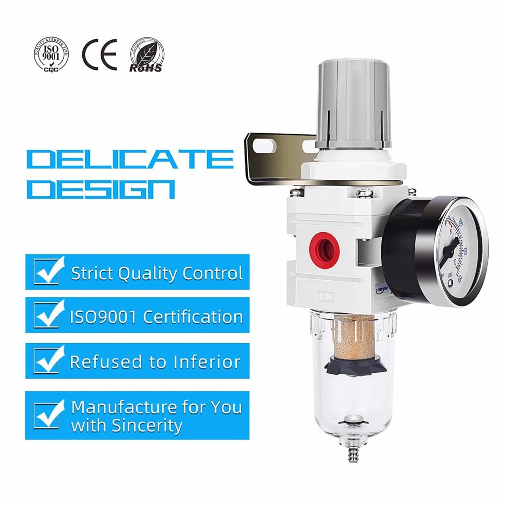
Filter / Regulator Combo
- Sets the station pressure your calculation assumed
- Keeps condensate out of cylinder seals
- Mounts at the machine, where regulation belongs

Regulator & Flow Control 0-150 PSI
- Run the lowest pressure that still makes the force
- Gauge makes the assumption checkable
- Station control instead of raising the whole header
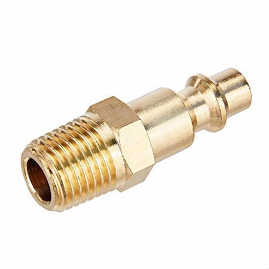
Quick Connect Brass Coupler Kit
- Undersized couplers starve a fast-cycling cylinder
- Same fitting standard at every station
- Brass resists the corrosion that shrinks bore
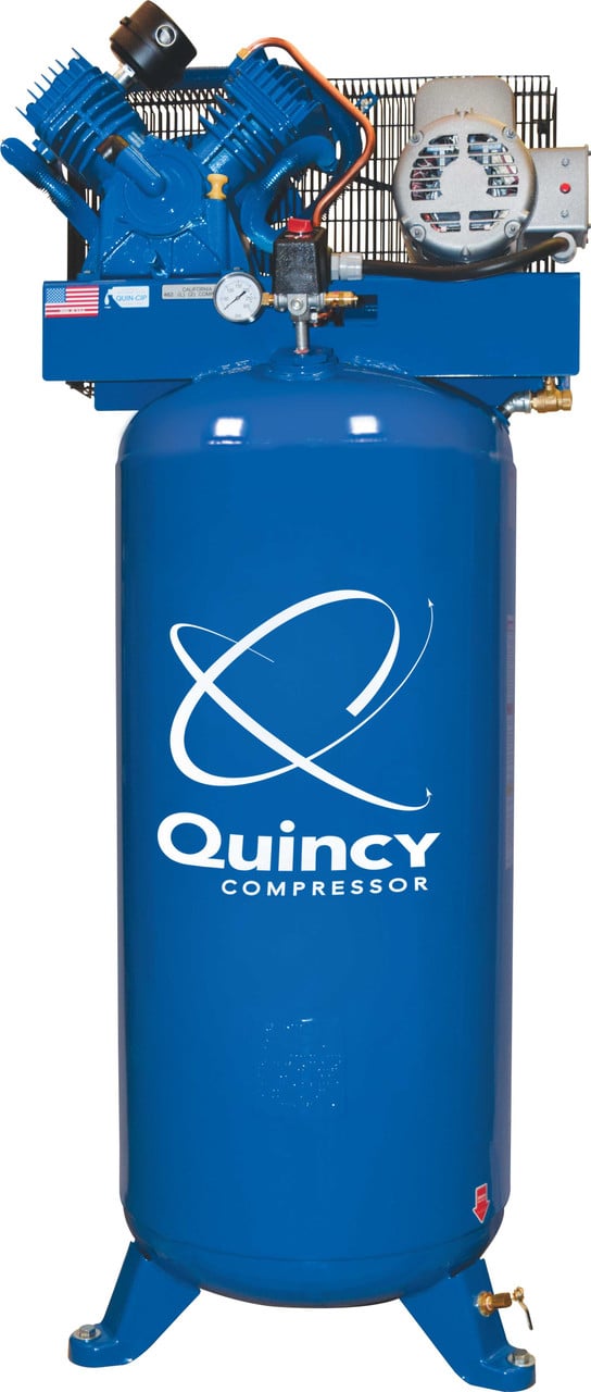
Quincy QT-54 5 HP 60-Gallon
- Continuous-duty supply for a continuously cycling cell
- Receiver volume absorbs per-cycle peaks
- Suits a small cell running several cylinders
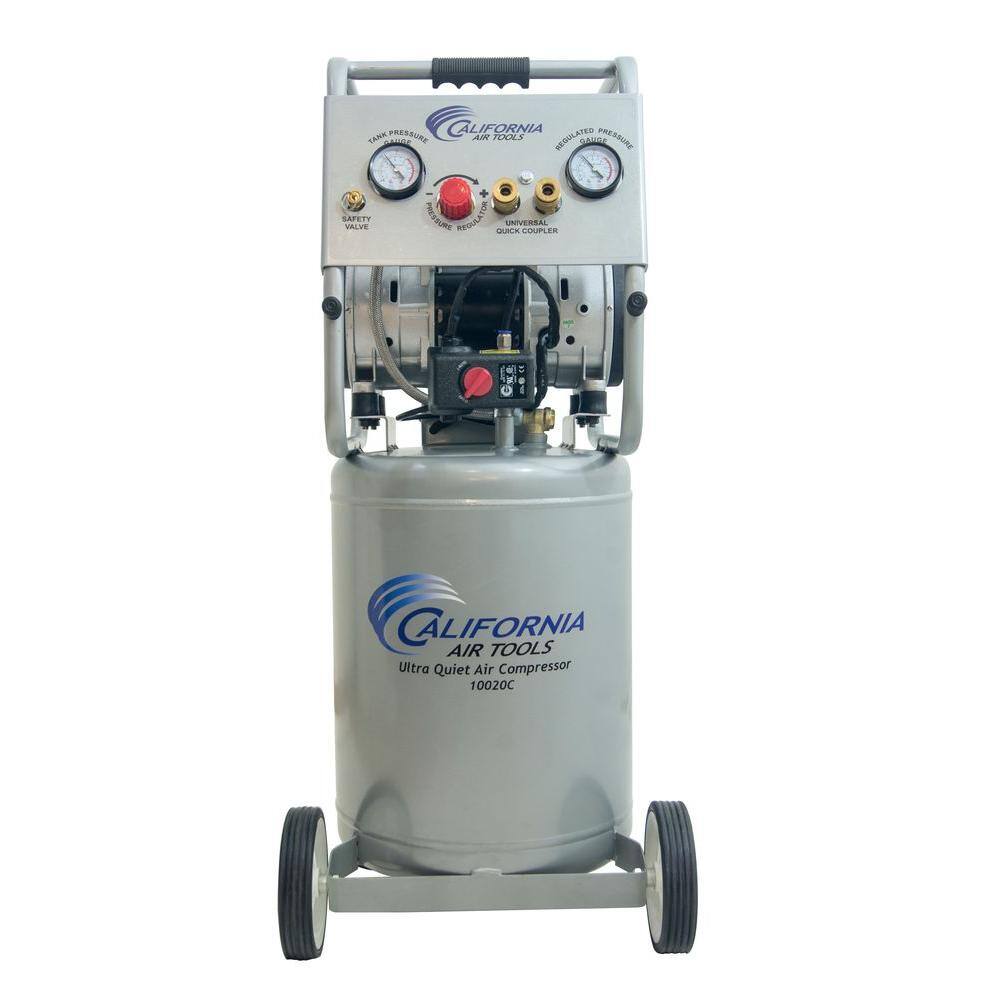
California Air Tools 10020CAD
- Low-SCFM cells running beside people all day
- Auto drain keeps water out of the cylinder feed
- Oil-free, so nothing carries over onto the work
As an Amazon Associate, TestTalkHQ earns from qualifying purchases. Prices and availability can change.
Peak draw, and why the receiver does the hard part
Here is the thing that surprises people who have only ever done the SCFM arithmetic. The 4 inch bore, 6 inch stroke press above consumes about 0.28 standard cubic feet on its extend stroke alone. If that stroke takes 0.4 seconds, the flow rate during the stroke is roughly 0.28 × (60 / 0.4) = about 42 SCFM — while the same cylinder averaged over its full cycle at 30 cycles a minute draws about 17 SCFM.
Nobody buys a 42 SCFM compressor for that cylinder. The receiver supplies the peak and the compressor refills it between strokes. That is the entire purpose of the tank, and it is why a small compressor with adequate storage will beat a larger one with none.
Two practical checks on storage:
- Pressure sag during a stroke. Put a gauge at the machine’s regulator inlet and watch it while the machine cycles. A few psi of movement is normal. A visible dive that recovers slowly means the local supply cannot keep up with the peak, whatever the compressor nameplate says.
- Compressor cycling frequency. A reciprocating unit starting more than a handful of times an hour is short-cycling. That is a storage problem far more often than a capacity problem.
The air compressor tank size calculator handles the storage half of this, and the pipe size calculator makes sure the peak can physically get down the line.
Choose the operating pressure before you choose the compressor
Pressure is the input that quietly sets everything else. Because free air consumption scales with absolute pressure, dropping a station from 100 psig to 70 psig cuts its air consumption by about 26 percent for the same cylinder — while cutting its force by 30 percent. If the force was never needed, that is free money.
The right sequence is: work out the force each cylinder genuinely has to produce, pick the lowest pressure that produces it with sensible margin, then size the compressor for the resulting air. Doing it in the other order — buying the compressor, setting it to 120 psig because that is what it does, and regulating down at every station — is how most shops end up paying for air they throw away.
Do not size for speed with an SCFM number
Air consumption and cylinder speed are unrelated calculations and people conflate them constantly. Consumption is a volume question answered in SCFM. Speed is a flow-restriction question answered in valve and fitting Cv, tube bore, and port size. A cylinder can have all the SCFM in the world available and still crawl because it is fed through an undersized valve, a flow control screwed most of the way shut, or a clogged muffler on the exhaust port.
If the complaint is “it is too slow”, nothing on this page will fix it. Start at the exhaust side — a restricted exhaust is the most common and most overlooked cause.
Commission with a measurement, not a calculation
Every number above is an estimate. Once the machine runs, spend an hour turning it into a measurement, because that is what you will rely on for the next expansion.
- Isolate the machine on its own drop with a ball valve, if it is not already.
- Record the regulator setting actually in use, not the one on the drawing. It is rarely the same.
- Measure the cycle rate with a stopwatch over a few minutes rather than trusting the HMI figure.
- Compare against the schedule. Re-run the calculator with the measured pressure and rate. If reality is more than about 20 percent above the prediction, you have a leak, an air-consuming device nobody told you about, or a blow-off that is not in the schedule.
- Write the result on the machine. A laminated card with measured SCFM, pressure and rate saves the next person the entire exercise.
Keep the schedule file. When someone adds a station in two years, the argument about whether the compressor can take it becomes a five-minute addition instead of a fortnight of speculation.