Boring-bar starting SFM by workpiece and bar material, finish-pass IPR bands, and L/D stick-out guidance — with enough setup context to use the tables without treating them as a second calculator.
How to Use This Chart
These tables are planning baselines for single-point boring on a lathe (or a mill with a boring head). They do not replace a print, a tooling data sheet, or a trial cut on scrap. Convert SFM to spindle speed with RPM = SFM × 3.82 ÷ bore diameter (inches). Then check overhang ÷ bar diameter (L/D) before you push feed — a perfect SFM still chatters at 6:1 stick-out on a conventional bar.
Use the interactive boring bar calculator when you want RPM, feed, depth of cut, and L/D risk on one screen. Use the boring bar guide for formulas, spring-pass finish strategy, and material notes. This chart page is the printable/reference table set with the prose you need to interpret it.
What This Chart Is — and What the Calculator Already Does
The calculator solves a specific setup: you enter bore diameter, material, tool class, and overhang, and it returns recommended RPM/feed windows plus chatter risk. This chart does not re-run that solver. It publishes the underlying SFM bands, IPR finish bands, and L/D action thresholds so you can scan materials side-by-side, brief a helper, or mark a print without opening the tool.
If your question is “why is this bore failing,” go to boring bar troubleshooting. If your question is “solid vs indexable vs head vs damped,” go to boring bar types — which for the job. Keep OD turning separate: the lathe turning chart is for external cuts with different stiffness and chip flow.
SFM by Workpiece & Bar
SFM is surface speed at the bore wall. Carbide generally runs much faster than HSS. Sticky or work-hardening alloys (stainless, titanium) sit at the low end; aluminum sits high. Hardened steel is carbide-only in this table for a reason — HSS will not hold an edge at useful rates.
| Workpiece | HSS bar SFM | Carbide bar SFM |
|---|---|---|
| Mild steel | 80–100 | 300–500 |
| Stainless | 40–60 | 150–250 |
| Aluminum | 200–300 | 600–1000 |
| Cast iron | 60–80 | 200–350 |
| Brass | 150–200 | 400–600 |
| Titanium | 20–30 | 100–150 |
| Hardened steel | — | 50–100 |
Start mid-band on a stiff setup (L/D under 3:1). On caution L/D (3:1–4:1), bias toward the low end of SFM and reduce feed 20–30%. On deep reaches, fix stick-out or move to a damped bar before chasing the top of the carbide column.
Feed IPR by Finish Pass
Feed per revolution dominates theoretical surface finish and also changes chip thickness. Roughing removes stock; finishing sets Ra; a spring pass (same X, no extra infeed) picks up deflection after the first finish cut.
| Pass | IPR range | Typical mid |
|---|---|---|
| Roughing | 0.005–0.015 | 0.010 |
| Semi-finish | 0.002–0.005 | 0.003 |
| Finishing | 0.0005–0.002 | 0.001 |
On stainless, avoid feather-light feeds that rub and work-harden — keep the edge cutting. On aluminum, pair finish IPR with flood coolant or chip clearing so soft chips do not weld and score the ID.
L/D Stick-Out Guidance
L/D = unsupported overhang length ÷ bar diameter. It is the single best predictor of chatter risk in boring. Halving stick-out multiplies stiffness dramatically; upsizing diameter helps almost as much when bore clearance allows.
| L/D ratio | Risk | Action |
|---|---|---|
| Under 3:1 | Stable | Run recommended SFM/feed |
| 3:1 to 4:1 | Caution | Reduce feed 20–30% |
| Over 4:1 | High chatter risk | Shorten stick-out or anti-vibration bar |
Conventional solid and indexable bars live under the 4:1 line for production work. Anti-vibration (damped) bars extend usable reach when depth is real and stick-out cannot shrink. Selection detail: which boring bar type for the job.
Reading the Tables Together
Pick SFM from material and tool class, convert to RPM for the actual bore diameter, choose IPR for the pass type, then gate the whole setup through L/D. If L/D fails, do not “save” the cut by only dropping SFM — change stick-out, shank size, or bar type. If diameter comes in light after a finish pass, run a spring pass before you rewrite the SFM table. If chips pack in a blind bore, interrupt the feed and clear — that failure mode is boring-specific and will not show up the same way on an OD turning chart.
Get SFM, RPM, feed, and L/D risk
WeldKit — Welding Calculators Offline
MIG, TIG, Stick, speeds/feeds, and more on Android.
Related Calculators & Guides
Machining
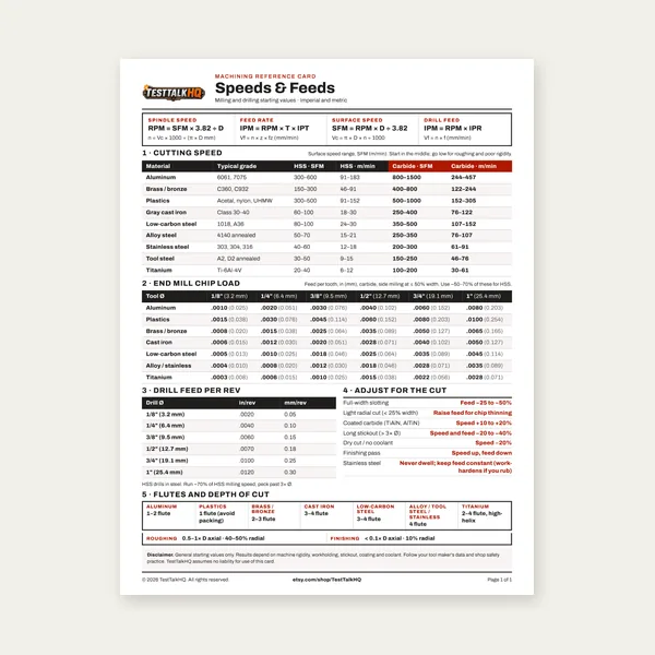
Machining Speeds & Feeds Card
One page. Speeds, chip load and drill feed, imperial and metric.
$3.99
Buy
Complete Machining Speeds & Feeds Guide
27 pages. Milling, drilling, tapping, turning and CNC routing.
$12.99
Buy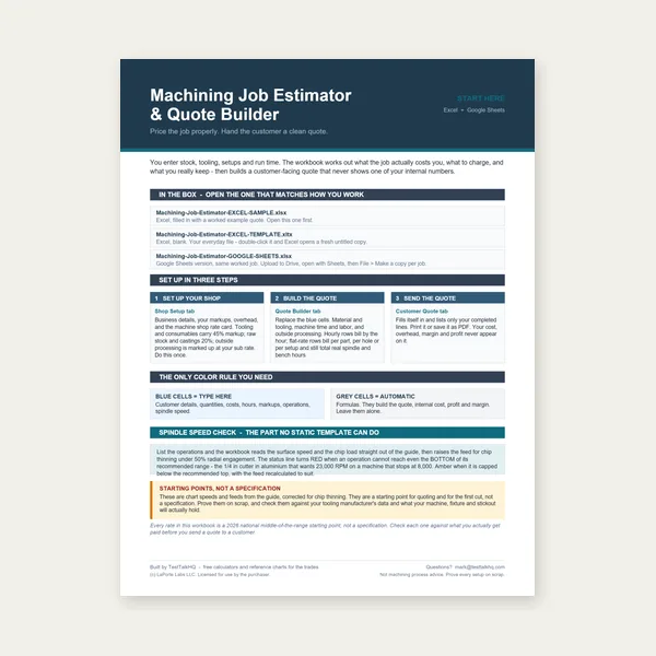
Machining Job Estimator
Quote shop work and check operations against your spindle's top speed.
Excel or Google Sheets. Best on a computer.
$29.00
Buy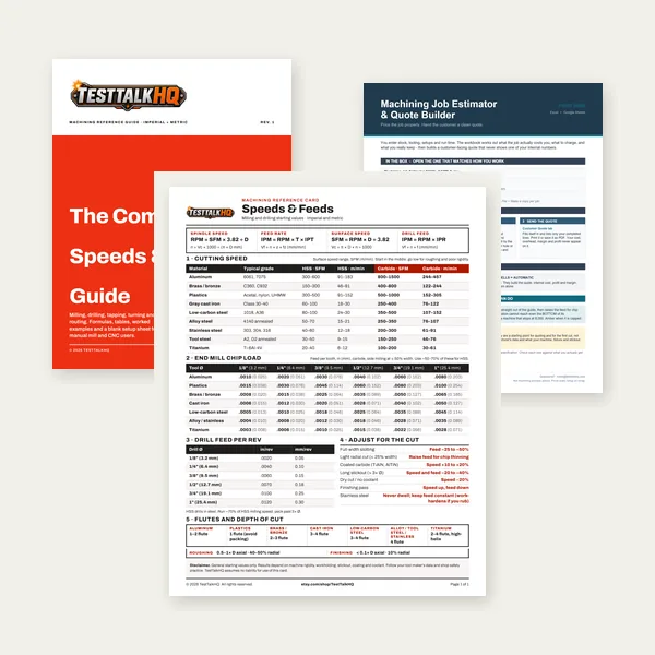
Machining Complete Bundle
Card, 27-page guide and the estimator workbook. All six files.
Excel or Google Sheets. Best on a computer.
$34.99
$45.98 if bought separately — save $10.99
BuyCheckout opens in a new tab.