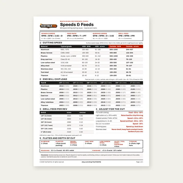
Machining Speeds & Feeds Card
One page. Speeds, chip load and drill feed, imperial and metric.
$3.99
BuyRPM, Feed Rate & Chatter Fix for any material
Setting boring bar speeds and feeds is where finish, tolerance, and tool life are won or lost on a lathe. This guide walks RPM and feed-rate formulas, chatter and L/D ratio fixes, material-specific tips, and surface finish strategy.
Use it alongside the Boring Bar Speed and Feed Calculator to dial in RPM, feed rate, and depth of cut before you cut.
Boring is the operation of enlarging an existing hole with a single-point cutting tool to achieve a precise diameter, location, and surface finish. A drill creates the starting hole but cannot hold tight diameter tolerance, cannot guarantee roundness, and cannot correct positional error — the drill follows the lead it found at start. A reamer improves finish and diameter on a hole already in the right place, but it follows the existing hole rather than correcting it. A boring bar is the only one of the three that can independently set diameter and position.
Reach for boring when: you need a non-standard diameter, you need tolerance tighter than ±0.002", you are fitting a bearing or bushing to a specific class of fit, the part has runout that must be cleaned up, or you need a controlled surface finish for a sealing surface. Reach for reaming when: the hole is already in position and you only need finish and diameter on a standard size. Reach for drilling alone when: tolerance is open and finish does not matter.
Solid carbide boring bars are stiff for their diameter and the right choice for small bores and short-to-medium overhangs. The tip is brazed or ground integral to the shank.
Indexable boring bars use replaceable carbide inserts (CCMT, DCMT, TPGB). They are the workhorse for bores above about 0.5" and let you change insert grade and geometry for different materials without changing the bar.
Boring heads mount in a mill spindle and let you precisely dial in diameter via an adjustable cutter slide. Use them when the work is on a mill instead of a lathe, when the bore is offset from the part centerline, or when the part is too large to swing in a chuck.
Anti-vibration (damped) boring bars have an internal tungsten mass damper tuned to absorb the bar's natural resonant frequency. They extend the workable L/D ratio from a typical 4:1 limit out to 7:1 or 10:1. They are the engineering answer to deep bores that would chatter with a conventional bar.
The formula is the standard surface footage equation, adapted for the bore diameter rather than tool diameter:
SFM (surface feet per minute) comes from the material/tooling table. The 3.82 constant converts SFM and inches into revolutions per minute. Feed rate is independent of RPM — it is set as IPR (inches per revolution), typically 0.005–0.015 for roughing, 0.002–0.005 for semi-finish, and 0.0005–0.002 for finish.
Skip the mathThe calculator outputs RPM, feed rate, depth of cut, and L/D chatter risk in one screen.
Open Calculator →Chatter is a self-sustaining vibration that occurs when cutting force exceeds the static and dynamic stiffness of the boring bar. The resonant frequency builds, the insert lifts and re-engages the work, and the bore wall ends up with a regular chatter pattern that cannot be polished out.
L/D ratio is the single most predictive variable. Overhang divided by bar diameter. Under 3:1 a conventional bar is stable. Between 3:1 and 4:1 you must back the feed off 20–30% and lighten depth of cut. Above 4:1 you are out of conventional-bar territory — use an anti-vibration bar or change the setup.
Fixes in order of effectiveness:
Run carbide at 300–500 SFM, HSS at 80–100 SFM. Mild steel is forgiving — feed and depth matter more than chasing the top of the SFM range. Aggressive cutting fluid keeps chips moving out of the bore.
Run carbide at 150–250 SFM. Stainless work-hardens — never dwell, never let the insert rub. Keep feed up (toward 0.005 IPR even for semi-finish) so the insert is cutting fresh material every revolution. Sharp positive-rake inserts are non-negotiable on 304/316.
Run carbide at 600–1000 SFM, HSS at 200–300 SFM. Aluminum welds to the insert face if heat builds — use cutting fluid aggressively and choose inserts with polished rake faces. Honed HSS produces excellent finish at modest speeds.
Run carbide at 200–350 SFM, dry. Cast iron generates dust rather than chips and cutting fluid creates a slurry that wears the insert faster. Dust extraction is recommended for production work.
Run carbide at 100–150 SFM only. Titanium is unforgiving — high speed produces heat the chip cannot carry away, the insert work-hardens the surface, and tool life collapses. Use the calculator set to titanium for conservative starting values, and run flood coolant. Never dwell.
Surface finish on a boring pass is driven primarily by three variables: feed rate per revolution, insert nose radius, and bar deflection. The theoretical finish formula is:
At 0.001 IPR with a 1/64" (0.0156") nose radius, the theoretical Ra is approximately 20 µin — production-quality finish. At 0.005 IPR with the same insert, theoretical Ra jumps to 500 µin and the surface looks turned, not bored.
Practical strategy: rough to 0.020"–0.030" oversize at aggressive feed, take a finishing pass at 0.010" oversize with finish-grade feed, then take a spring pass with the same X setting and zero additional infeed. The bar deflects under load during the first finishing pass; the spring pass picks up the 0.001"–0.003" the bar pulled away. Use flood coolant on the finishing pass to prevent chip welding on the insert face.
4:1 is the practical limit for standard solid carbide or HSS bars. Anti-vibration boring bars extend this to 7:1–10:1 because the internal damper absorbs the resonant frequency before it builds.
Yes — HSS can produce excellent finish on aluminum at 200–300 SFM. A sharp HSS tool honed to a keen edge produces near-mirror finish on a finishing pass. Use cutting oil aggressively to prevent aluminum from welding to the cutting edge.
On a lathe with automatic feed, set feed directly in IPR via the gearbox or CNC parameter (G99 on most controls). On a manual lathe with no feed readout, time the carriage over a known distance and calculate IPR manually.
Use a boring head on a mill when the hole is offset from the part centerline, the part is too large to chuck, you need multiple holes in one setup, or you need a blind bore with precise location. The same RPM formula applies — bore diameter and SFM drive the speed.
Ready to set up your next bore?The Boring Bar Speed and Feed Calculator outputs RPM, feed rate, depth of cut, and L/D chatter risk in one screen.
Open Calculator →Boring Bar Troubleshooting for symptom diagnosis. Boring Bar Types — Which for the Job for solid vs indexable vs head vs damped.
One page. Speeds, chip load and drill feed, imperial and metric.
$3.99
Buy
27 pages. Milling, drilling, tapping, turning and CNC routing.
$12.99
Buy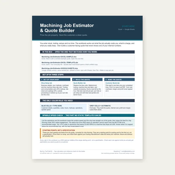
Quote shop work and check operations against your spindle's top speed.
Excel or Google Sheets. Best on a computer.
$29.00
Buy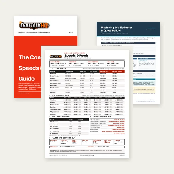
Card, 27-page guide and the estimator workbook. All six files.
Excel or Google Sheets. Best on a computer.
$34.99
$45.98 if bought separately — save $10.99
BuyCheckout opens in a new tab.